This document is a description of my experience as a system’s programmer for the Fire Department of the City of New York. In that role I was solely responsible for the maintenance and management of the operating system for the department’s Starfire computer-aided dispatch system. I eventually became the manager of the team that supported Starfire including application developers and staff responsible for numerous data sources that the system depended on. I am describing the operating system completely from memory. I have not seen source code for this system since 1997. I have access to the PDP-11/70 processor handbook along with a number of device user guides, which helps putting it all together.
This document focuses on my experience with the custom operating system CMICS, that supported Starfire because it led me to maintain and update the actual operating source code. Through my twenty year working with OpenVMS, I used system services such as Asynchronous System Traps, QIO’s, and Mailboxes. Under Windows I implemented threads for Internet aware applications. I thus expanded my knowledge of modern, real-time, operating systems.
The Period Of The Late 1960’S To The Early 1970’S, For The Fire Department Of New York City, Was Known As The “War Years” (#3 War Years). The Volume Put The Existing Manual Processes Under Extreme Strain (#9 A Brief History of the 1970's Fire Service). The Department Decided To Write Requirements For A Computer-Assisted Dispatch System, The First Of It’s Kind In The Country.
Bradford National Corporation was awarded the contract. A Demonstration System Was Put Into Production Supporting The Borough Of Brooklyn Only. Some Of The Special Devices Were Created At The Start Of The Brooklyn System. These Include The Use Of Existing Cabling To Communicate Between The Central Computer And The Firehouses, The Design Of The Device That Was Installed In The Firehouse For Receiving And Acknowledging Incident Assignments, The Use Of A Mini-Computer Instead Of A Mainframe, And Finally The Creation Of A Custom Operating System Instead of a Commercially Available One.
The Design Of The System Benefited From An Earlier Study Performed By The Rand Corporation That Looked At Unit Deployment, Relocations Of Units To Cover Areas Where Units Were Working At Fires, And Workflow In The Dispatch Center. This Study Produced A Fairly Efficient Manual Process For Processing Calls From The Public And Tracking Units. The Computer System Design Was Written To Support The Existing Workflow While Allowing Quicker And More Accurate Decisions And Keeping Track Of Units Without Requiring The Dispatchers To Write Things On Paper For Later Reference.
The Starfire system was actually a collection of dozens of individual applications which were run under the CMICS (Central Management and Incident Control System) operating system. Going forward I will use CMICS to refer to the Operating System and Starfire to refer to the combination of Operating System and Application programs.
In 2000 the Starfire system was converted to run under VAX/VMS. The conversion retained much of the original system constraints while introducing a new one. The new restraint is that the converted system ran as a single executable. Since this conversion made use of the existing operating system, the CMICS portion of Starfire was eliminated. I have access to copies of the OpenVMS applications and I am able to refer to these modules to refresh my memory on the CMICS versions of them.
1 - Introduction
1.1 - Starfire
The dispatch system was given the name Starfire. It fits given that it was designed to dispatch fire units to fires and the physical configuration of a five-pointer star. This name encompassed the central system, both the custom operating system and the application level software. The name also covered the computers that were the borough concentrators, the micro-computers that supported the sub-systems, and the peripherals such as workstations, printers, and display boards. The operating system was called CMICS, or Central Management Information and Control System.
The Brooklyn demonstration system was implemented on a PDP-11/45. The citywide system was initially implemented on PDP-11/70 which were eventually replaced with PDP-11/84.
For most of the 20th century, fire dispatching in New York City was divided into five boroughs, with a physical dispatch center in each borough. This was a good solution to the distance problem when the first street fire boxes were installed. The cables were run to a central location in each borough. The original street boxes included spring-loaded, toothed wheels that, when pulled, rotated interrupting the cable circuit based on the teeth in the box. The teeth were patterned to ring a unique numeric pattern that could be distinguished by the dispatchers in the CO (communications office). Box 1756 on the corner of Amsterdam Ave and W 100 St would ring in the CO, one time, pause, seven times, pause, five times, pause, and finally six time.
When Starfire was being designed it was understood that the deployment of the dispatchers in the five communications offices would be retained. This was convenient in that the cabling for the street boxes all formed up there as well as the cabling for the intercom system that had been used to communicate between the dispatchers and the firehouses. Some of the spare cables for this intercom system were re-purposed to support the data communications between the CO and the firehouse.
The central computers for the citywide system were located at the department’s data center on the grounds of Police Headquarters. These would be the PDP-11/70s. Since there were large amounts of equipment located in each communications office, less powerful computers, PDP-11/34s were installed there. The central systems had very little peripheral equipment connected. Instead, high-capacity synchronous communications links were installed between the 11/70s at central and the 11/34s in the COs. These were called concentrators. The peripheral equipment used by the dispatchers, workstations, and printers were all connected to the concentrators and the messaging between the peripherals and the central systems were put on the high-speed synchronous lines to central.
The CO’s also housed the micro-computers that supported the street boxes. A computer was designed that relieved the dispatcher of the requirement to listen for the rings of the street boxes. Instead the interruptions of the circuits caused by the wheels in the boxes were processed silently by the micro-computers and delivered to the central system. The central system, in turn, notified the dispatchers in the CO that a box had been pulled.
During this time and modern version of the street boxes had been designed and implemented partially around the city. This system, known as ERS, allowed the person in the street requesting help, to speak to a dispatcher directly and describe what help they needed. This system also included a micro-processor that notified the central system when a box had been pressed. The call taker who fielded the call would add information derived from the caller to the call mask which would become part of the incident record.
Finally, a third micro-computer system was built for each CO that helped the dispatchers interaction with Starfire. This system, known as SRS (Status Reporting System) included a colored map showing a simplified indication of the status of each unit, a specialized keyboard designed for efficient entry of incident and unit status information into the system, and a chipboard that supported manual operations as a backup. Previously the dispatchers used a chipboard to track the units and incidents. The center of the board had rows of empty slots that would be dedicated to a fire, small or large. On the sides of the board were slots holding chips that were labeled with the name of the units in the borough. When a fire occurred, the identifier of the incident was written along the left side of a row of empty slots and the chips representing the units assigned to the fire were moved from the normal location on the side into a slot associated with the fire. When units were released from a fire the chip would be moved back to their normal location. Starfire and the new SRS system supported this manual process by having small led’s below each unit’s chip that reflected their ambient status. Additionally, a status report was printed every five minutes that listed all open incidents and the units assigned. The report also included any unit that was not assigned to an incident but was not available for some reason. This supported the dispatcher’s quick shift to the manual method should the system become unavailable with units at fires.
This makes three micro-computer systems plus the workstations and printers that were connected to the concentrators in each of the five communications offices. The concentrators also ran a custom operating system although it was so slimmed down that there really was no distinction between OS and application software and there was no command line prompt or user interface.
When Starfire was originally planned the application was to run under RSX-11D, a commercially available and reliable operating system for the PDP-11 Family. The results of a proof-of-concept installation in the borough of Brooklyn showed that the system did not perform well enough to support the whole city, even after migrating to an 11/70 from the 11/45. It was determined that the hardware architecture was sufficient to provide the required performance and that the operating system was where the performance was lost. The contractor
enough of the original design was sufficient, that the planned hardware, and software was retained. The improvement in performance was gained through writing a custom operating system that trimmed any unnecessary functionality
1.2 - Starfire Systems Programmer
I had been exposed to a PDP-8/s while in high school in 1969. We had to load the operating system via the paper tape reader attached to the teletype. The teletype was the only device interfaced to the system until we got a high-speed paper tape reader.
The initial citywide equipment installations were underway when I joined FDNY in August of 1979. I had joined under an administrative title working for the bureau of communications. This bureau included the fire-alarm dispatchers. My work location was the dispatching office for Manhattan which was located in Central Park. I had an opportunity to see the computers they were installing. The front panel of the systems were very familiar to me since we had to use the toggle switches to load the operating system at school. This familiarity led me to pursue a transfer into the computer bureau. The Assistant Chief was supportive of my request and endeavored to make my transfer possible.
After transferring to be an application programmer, I was asked by the vendor if I wanted to become a systems programmer. The reason was because the city had decided to bring the contract to an end, leaving six to ten weeks to close out the project. The citywide installation was complete even through there were many outstanding issues, like the system, crashing on a regular basis.
I agreed although I did not really know what that meant. I agreed, of course. My first task was to read the PDP-11/70 Processor Handbook (#4 PDP-11/70 Processor Handbook) from front to back. I was told I would not understand most of what I read, but go through it until the end. Once I completed that the project manager introduced me to each of the major sections of the operating system and the modules that made up each section. He then walked me through a system dump to familiarize me with the system resources and how to find them.
Then the contract end date passed and the vendor was gone. It was an interesting situation. There was no contract with any vendor, so I could not call them for help when I got into trouble. There was a maintenance contract with Digital Equipment Corporation. Through that contract I could get information about the equipment we were using. This contract also provided regular preventive maintenance. The software support service could help me understand how a particular instruction worked or how an interface card should behave in normal circumstances. But since the operating system was written specifically for the Fire Department, software support could not help me to diagnose issues. I had to figure everything out myself. What had I gotten myself into?
2 - Starfire System
2.1 - Overview
The Starfire central system consisted of the PDP-11/70 Computer, The RP06 Mass Storage Drive (#1 RP06 Disk Drive), the RS04 Fixed-head drives (#2 RS04 Disk Drive), A TU16 Tape Drive, console, and line printer. The RP06 hosted all the executable files, and the data files. Some of these files are read only at system boot time, some are read-only through the course of the system, and some are read and updated. The RS04 fixed-head drives are used to host the checkpoint files. The checkpoint files are updated constantly as incidents are opened and managed and as unit statuses are received and processed. The checkpoints allow Starfire to recover from a system restart while retaining enough live information such that any open incidents remain in the open status, and unit statuses are retained. This restart mode is called “Warm”. Because the checkpoints are written frequently and for every significant event, there were hosted on the fixed-head drives which were much faster than the moving-head RP06. The RS04 had a 25% higher transfer rate and it’s seek time was 4.5 times as fast.
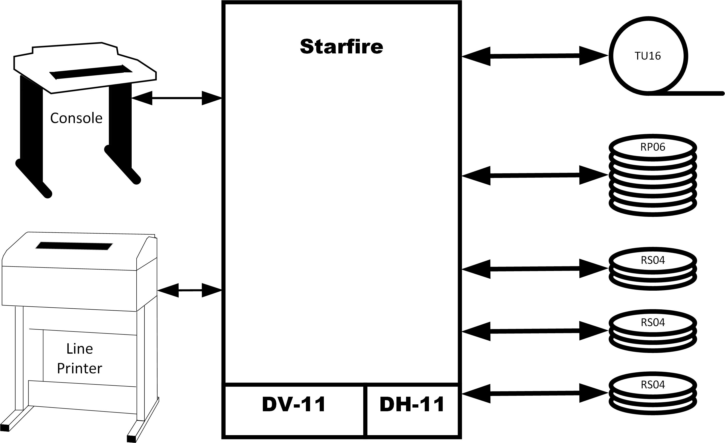
Figure 1 Starfire Central System
The name Starfire comes from the overall configuration of the system. New York City consists of five boroughs and the Fire units were dispatched out of the dispatch center for the designated borough. The main system computer equipment was located in a single, central facility which had data links to each of the five dispatch centers, while none of the borough centers were connected to each other. This results in a five-pointed star configuration.
The central computer, running CMICS and the application programs, handles the processing of all transactions and maintains the incident and unit status information. It communicates with six concentrators which, in turn, interact with the borough-specific sub-systems and the dispatchers. There are five boroughs and then a sixth one, called Central, which supports administrative and monitoring functions. This configuration relieves the central system from the requirement of monitoring the status of individual devices and the burden of managing the queues of these devices. When the mobile data terminal project was implemented, it was decided that the connection to Starfire would be with the central computers since there was a single radio-network controller that communicated with all devices.
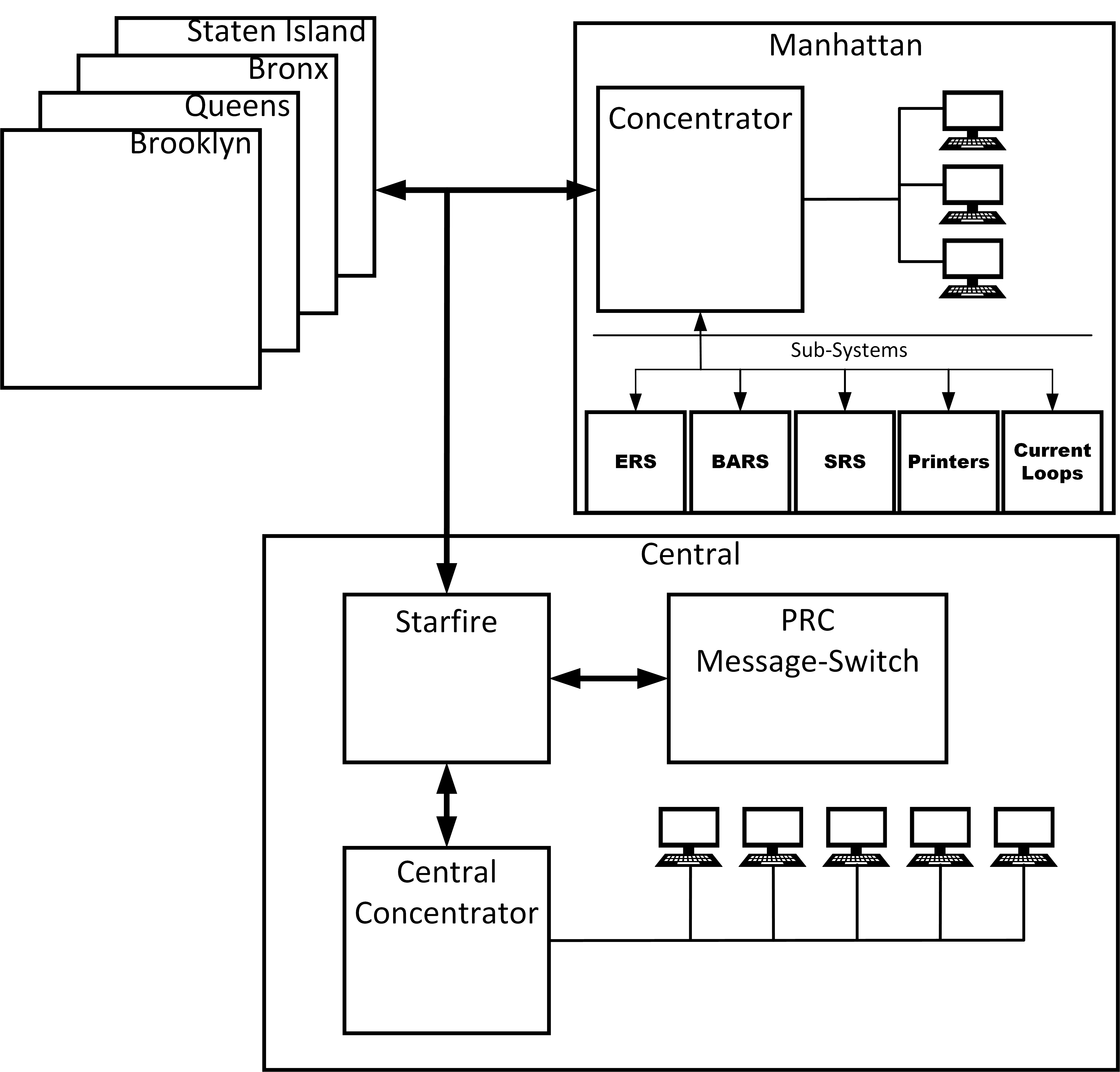
Figure 2 Starfire High Level Configuration
The name Starfire comes from the overall configuration of the system. New York City consists of five boroughs and the Fire units were dispatched out of the dispatch center for the designated borough. The main system computer equipment was located in a single, central facility which had data links to each of the five dispatch centers, while none of the borough centers were connected to each other. This results in a five-pointed star configuration.
The central computer, running CMICS and the application programs, handles the processing of all transactions and maintains the incident and unit status information. It communicates with six concentrators which, in turn, interact with the borough-specific sub-systems and the dispatchers. There are five boroughs and then a sixth one, called Central, which supports administrative and monitoring functions. This configuration relieves the central system from the requirement of monitoring the status of individual devices and the burden of managing the queues of these devices. When the mobile data terminal project was implemented, it was decided that the connection to Starfire would be with the central computers since there was a single radio-network controller that communicated with all devices.
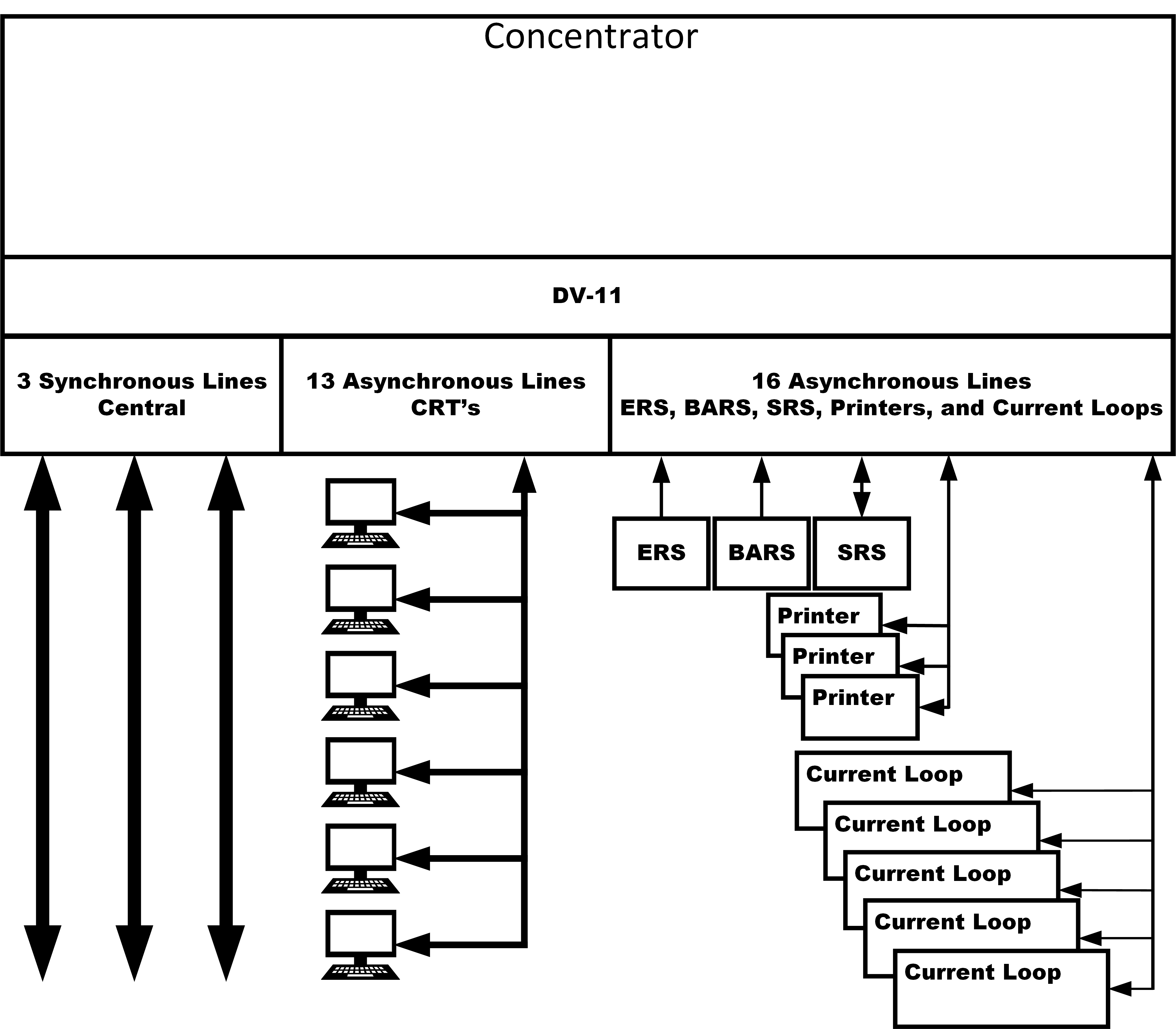
Figure 3 Typical Borough Configuration
The “Concentrator” was an embedded application that ran on an PDP-11/34. It handled the communications between itself and the Starfire Central computer using three 9600 Baud Synchronous lines implementing the DDCMP protocol. The physical transport was three synchronous circuits provided by NYNEX with Racal-Milgo modems at either end. The communication with all the other devices were asynchronous using non-standard protocols designed for the occasion. The DV-11 could be configured for each and there was no other device as part of the configuration. There was also no console or printer for system management. All devices were dedicated to operational activities.
2.2 - Starfire Operational Considerations
Starfire was known as a Computer-Aided Dispatch system, or CAD. It supported this function superbly. But at it’s core, Starfire was a communications system. This is an appropriate label, because, once an assignment decision had been made, the indicated unit(s) had to be notified of their assignment and the unit(s) had to deliver their acknowledgment of having been notified. Additionally, this had to be done in a timely manner because of the possibility that alternate notifications, or possibly, alternate assignments might be necessary and it was important to know this as early as possibly in the opening stages of a fire. For the early years of Starfire, there were normally three ways a dispatcher could get in touch with a unit. In 1991, a fourth means of communicating was added. Two of these methods are used when a company is located in their firehouse, and two are used when the company is on the road. The four methods are:
2.2.1 - Communications In the Firehouse
The primary method for contacting a company about their assignment is a physical device that prints a ticket including all the necessary information for the run. It is called an Alarm-Teleprinter/Selector. In addition to the printer it includes buttons for the company to press to acknowledge having received the assignment message and informing the dispatchers that they are responding to the incident. This acknowledgment is received by Starfire and the dispatcher is notified. The connectivity for this devices was provided by physical cables running through the street from the dispatch center to each firehouse. These were current-loop cables that reused cabling that had already been laid when the Starfire project was formed.
The backup means to notify a company in the firehouse is an intercom system that connects the dispatchers with each of the firehouses. On the dispatch platform is a console named Voice Dispatcher. The person occupying this position will use their console to connect to a firehouse or firehouses, to inform the companies of their assignment and the assignment details. The Voice dispatcher is queued by Starfire when they need to make such a notification. The connectivity for this system was provided by physical cables running through the street from the dispatch center to each firehouse. These were voice circuits that predated the Starfire project.
2.2.2 - Communications On the Road (On the Air)
Today the primary means of contacting a company that is on-the-air is through their Mobile-Data-Terminal (MDT). Like the ATS in the firehouse, this device includes a printer that produces a paper copy of the fire ticket, and buttons with which the company acknowledges having been assigned and informs the dispatchers that are responding to the incident.
The backup means to notify a company that is on-the-air is through the voice radio. On the dispatch platform is a console named Radio Dispatcher. The person occupying this position will use their console to connect to a firehouse or firehouses, to inform the companies of their assignment and the assignment details. The Radio Dispatcher is queued by Starfire when they need to make such a notification.
2.2.3 - Considerations Summary
In earlier days, the two backup methods had been the primary methods of contact. Once the modern methods were implemented, and with service-level standards for their performance, the measures for when the backup methods were to be employed were established.
It is for this reason that the instantaneous status of all communications paths and devices (where possible) were monitored and fall-back procedures designed and implemented. The ATS devices on the current loops were polled every three seconds and any change to the status of a device was reported back to Starfire. The individual MDT’s were not polled as they were part of a city-wide radio system that kept radio traffic to a minimum for the benefit of overall performance. However, the radio system itself was polled constantly, and the status of individual MDT’s was still maintained through available methods.
The programming features to support this monitoring and operational behavior will be seen throughout the system description that follows.
2.3 - PDP 11
2.3.1 - Processing Modes
The PDP-11 architecture supports three processing modes, 1) Kernel, 2) Supervisor, and 3) User. Each mode has a dedicated stack pointer. Only routines that are part of the operating system image run in Kernel mode. Supervisor and User mode tasks follow the same structure.
2.3.2 - MASSBUS
The PDP-11 MASSBUS was the communications path designated to support the devices that would require the highest amount of data throughput with a requirement for high speed. These would be the disk and tape drives. The MASSBUS supported the direct transfer of data between memory and the particular device. Main memory was accessed through cache memory control. The DV-11 was also designed to use the MASSBUS for data transfers. The RH70 connected through the UNIBUS to access device registers. The RH70 Special Massbus controller could support eight devices and the 11/70 could include as many as four RH70 controllers (#26 RH70 Special Massbus Controller).
For any device that was accessed through the RH70, the process of transferring data meant 1) establishing a location in memory for to hold the data, 2) specifying a data transfer size and maximum, 3) specifying any device specific information for the transfer, and 4) initiating the transfer. The processor could then focus on other things while the transfer was in progress. The transfer did not take place completely in the background, there was still a single path to accessing a particular memory location, but the coordination did not require the CPU to be involved. The processor could address cache at the same time the RH70 controller was addressing memory, but the CPU and the controller could not address memory at the same time, this had to be sequenced.
2.3.3 - UNIBUS
The UNIBUS was the communications path between the CPU and all devices installed on the computer. The following diagram shows the connectivity between the processor and the controllers through which each device is managed by the operating system.
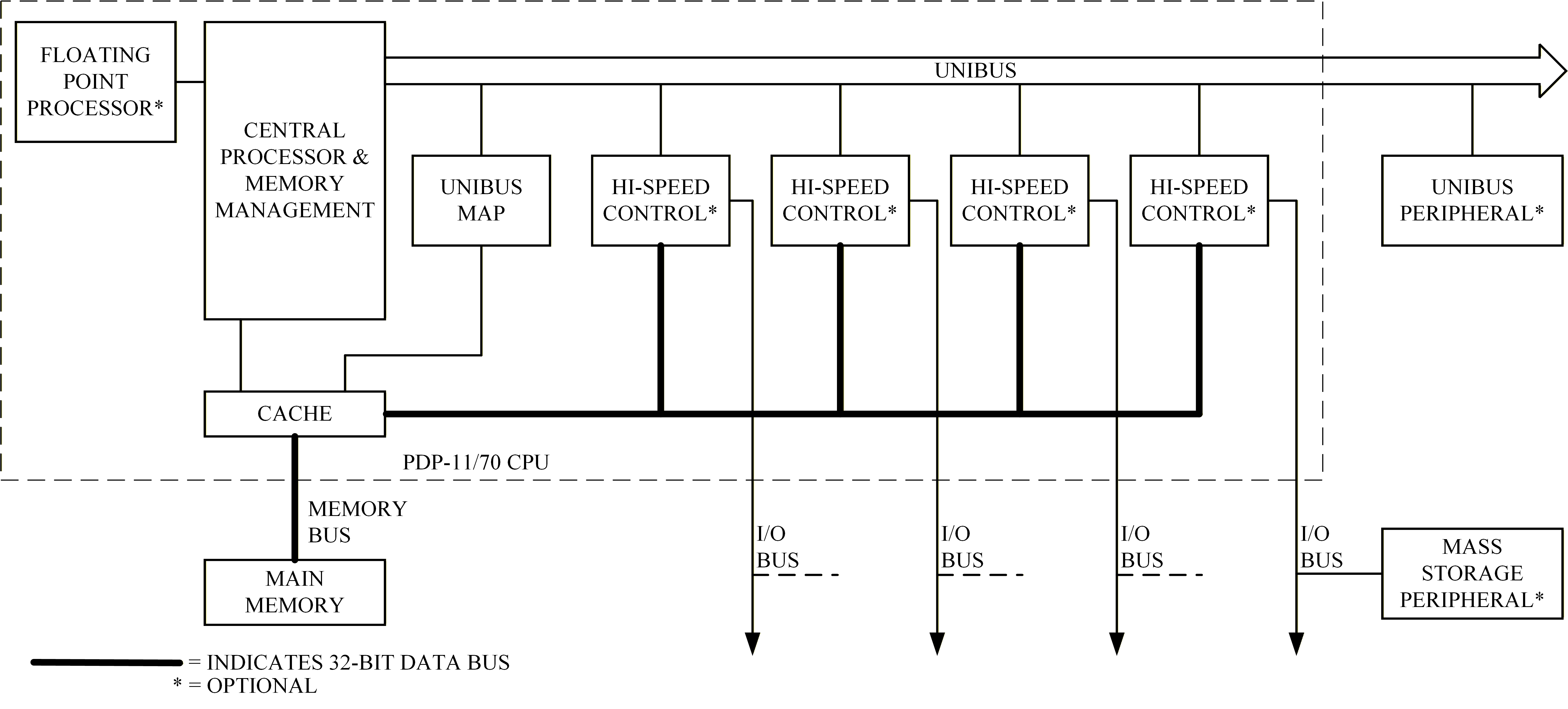
PDP 11/70 Block Diagram (#4 PDP-11/70 Processor Handbook pg 1-2)
The above diagram does not explicitly detail the RH70 massbus controller, but the bold lines between the “hi-speed” controllers and cache memory represent the 32-bit data bus that defines the MASSBUS.
2.3.4 - Interrupt And Trap Vectors
Occupying the very lowest of the systems address space is the Interrupt and Trap Vectors. At each interrupt address are two words, the first being the address of the interrupt service routine that will handle the interrupt request, and the second word is the value that will be applied to the processor status word.
|
Address |
Usage |
|
000 |
Reserved |
|
004 |
CPU Errors |
|
010 |
Illegal & Reserved Instructions |
|
014 |
BPT, Breakpoint Trap |
|
020 |
IOT, Input/Output Trap |
|
024 |
Power Failure |
|
030 |
EMT, Emulator Trap |
|
034 |
Trap Instruction |
|
~ |
|
|
060 |
Console Terminal / Keyboard/Reader |
|
064 |
Console Terminal / Printer Punch |
|
~ |
|
|
070 |
Paper Tape Reader |
|
074 |
Paper Tape Punch |
|
~ |
|
|
100 |
KW11-L Line Clock |
|
104 |
KW11-P Programmable Clock |
|
~ |
|
|
200 |
LP11 Line Printer |
|
204 |
RS04 Fixed Head Disk |
|
~ |
|
|
224 |
TU16 Magtape |
|
~ |
|
|
230 |
CD11 Card Reader |
|
~ |
|
|
240 |
Program Interrupt Request (PIRQ) |
Table 1 Interrupt and Trap Vectors
2.3.5 - Device Addresses
Occupying the very highest of the systems address space are the device addresses. These are the locations at which the operating system can issue commands to the device and receive data from the device. The architecture fixes the locations for a subset of available devices, such as the console, card readers, basic tape drives, common disk drives. This address space begins at 17765000 And ends at the very top, 17777776
|
Address |
Usage |
|
17777566 |
Console Terminal, printer / punch data |
|
17777564 |
Console Terminal, printer / punch status |
|
17777516 |
LP11 Printer Data |
|
17777516 |
LP11 Printer Status |
Table 2 Device Addresses
2.3.6 - Floating Vectors
Beginning at address 300 and extending to 777 are floating Interrupt Vectors. In this area the system expects trap vectors for a number of available devices. Instead of having the exact address defined, the architecture defines an installation order for these devices. This allows a wide variety of devices without dedicating memory space to unused devices. The devices in this set include the ability to set their interrupt address at the time of installation.
|
Rank |
Device |
|
1 |
DC11 |
|
2 |
KL11, DL11-A, DL11-B |
|
3 |
DP11 |
|
~ |
|
|
15 |
DH11 |
Table 3 FloatingInterruptVectors
2.3.7 - Floating Addresses
Beginning at address 17760010 and extending to 17763776 are floating device addresses. In this area the system expects trap vectors for a number of available devices. Instead of having the exact address defined, the architecture defines an installation order for these devices. This allows a wide variety of devices without dedicating memory space to unused devices. The devices in this set include the ability to set their address at the time of installation.
|
Rank |
Device |
First Address (if only floating address device in the system) |
|
1 |
DJ11 |
17760010 |
|
2 |
DH11 |
17760020 |
|
3 |
DQ11 |
17760030 |
|
4 |
DU11 |
17760040 |
Table 4 Floating Addresses
2.3.8 - Interrupt and Trap Handling
When an interrupt or trap occurs, the processor picks up a new program counter and a new processor status word at the designated location and transfers control using the new values. The interrupt or trap is requested by the appropriate condition or device. For instance, should an odd address error occur, the processor requests an interrupt to the address 004. If there is a loss of power, the processor will request an interrupt to the address 024. A device can request an interrupt. The interrupt address used by the processor is dependent on the requesting device. Devices such as the console and system clock have assigned addresses. Other devices use addresses within a range, and their position relative to others is specified by the manufacturer. This practice allows a high amount of flexibility for configuring a system based on the customers needs. FDNY used a fairly small number of devices and the configuration did not stress the designers. Some customers, particularly those who used their system to control floor devices and sensors like Nuclear Power Plants (#15 Nuclear Power Plant), likely had many devices installed. But they were accommodated through the floating address standard.
2.3.9 - Interrupt Service Routines
The Interrupt Service Routines are those routines that are given control when a specified devices issues a trap request. Depending on the device, this may be because it has data to deliver, has already written data into memory, or has completed delivering data externally. Interrupt Service Routines run in Kernel mode. The code for these routines are part of the operating system image, and thus, loaded when the OS image is loaded.
2.3.10 - Memory Management
Effective memory management plays an essential role in any system that employs multiple processes. “In a multiprogramming system, the ‘user’ part of memory is subdivided to accommodate multiple processes. The task of subdivision is carried out dynamically by the OS and is known as memory management.” (#16 Stallings, Computer Organization and Architecture pg 309).
One of the features of memory management is that each process can behave like it owns the computer system, or, better expressed, no process has to behave in such a way to avoid interfering with another process. The process has full control and access to the environment that it can see. To the operating system, each process has access to a section of memory, and that memory can actually exist anywhere within the user address space without requiring the process to behave differently. I over-simplify because each process does have to follow certain memory access procedures and rules. Also, the Starfire environment defines certain conventions that each process must follow. But between the architecture and application rules, the processes that constituted CMICS and Starfire (Task Model), were powerful and efficient.
2.3.10.1 - Memory Page
PDP 11 memory is addressed using a Page Address Register. Thus the area addressed by a PAR is called a Page. The maximum size of a page is 8192 bytes. Each PAR contains the address of the start of the memory page and the length of memory being addressed. There are 8 page address registers for each execution mode. The contents of the page address registers are part of the information that makes up a process and the set of information is unique to each process. Under CMICS, When a process is swapped out, for whatever reason, the contents of the page address registers are stored in the stack area for that process. When the swapped-out process is returned to the “running” state, the contents of the page address registers are restored from the process stack. In this way, the process resumes mapping the same locations in memory as when the last instruction was executed. Theoretically, these resources could have been moved around within memory between the time the process was suspended and restarted, but Starfire did not implement such features.
2.3.10.2 - Stack
Every supervisor and user mode task is assigned a stack. The stack is designed to support the two potential states for any task, A) suspended and B) running. In order to support transitioning a task from suspended to running, the stack contains the following information, 1) Program counter, which is the address of the next instruction to execute, 2) Program Status Word, 3) Stack Pointer, 4) The eight program registers, 5) the eight page address registers, 6) The resource number of any mapped resources, and 7) the stack contents. While the task is running the stack supports the task by being the location for any variables used by the application plus the items pushed onto the “stack” via the stack pointer (SP).
2.3.11 - PDP 11/70
The 11/70 was released on March 1975 (7 PDP-11/70 Minicomputer). Being an early model it used magnetic core memory. The disk drives were clones of Memorex drives which were clones of IBM drives. The PDP-11 family began in 1970 with the PDP-11/20. The 11/70, using a 22 bit address bus was able to support 4 MBytes of main memory. The word size was 16 bits. It contained 2k cache and supported direct memory access for storage devices through it’s Massbus. The 11/70 was part of the 3rd generations of PDP-11 models.
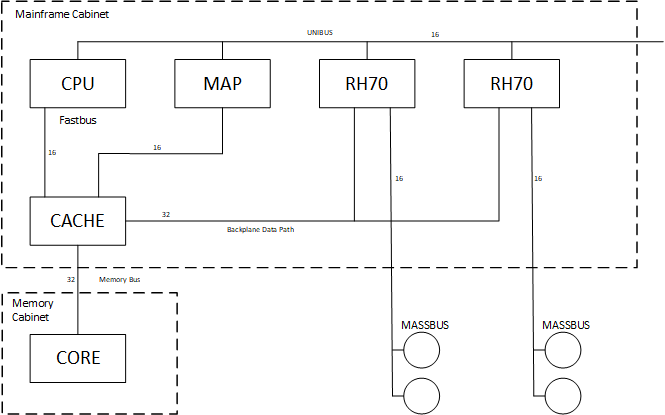
Figure 4 PDP-11/70 Configuration (#13 A DEC View of Hardware Systems Design pg 279)
The systems at FDNY, initially only had a system console for interactive communications. It had a card reader (#14 CR11 Card Reader) for source code maintenance. Then it had DEC LP11 Line Printer. The family of PDP-11’s were designed to provide varying levels of performance indexed to cost of ownership.
2.3.12 - PDP 11/84
The 11/84 was released in 1985. While it maintained the general PDP-11 Architecture, there were many differences from the 11/70. Two major differences were:
1. The Massbus was eliminated in favor of increased use of the UNIBUS plus use of PMI to speed memory access.
2. Solid State Memory.
When DEC designed the 11/84 they made a number of organizational changes to improve overall performance. They dropped the MASSBUS in favor of using the UNIBUS for all transfers. They created the Private Memory Interconnect and dedicated it to improving transfers between memory and the CPU (#6 PDP-11 UNIBUS Processor Handbook pg 2-4). The PMI included double-word transfers. It also allowed the CPU to access cache memory while DMA transfers were in progress, which was one of the features of the earlier MASSBUS.
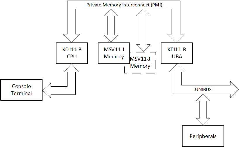
Figure 5 PDP-11/84 Block Diagram (#6 PDP-11 UNIBUS Processor Handbook pg 2-3)
Eliminating the MASSBUS meant that the transfers between data devices such as the disk and tape drives would have to take place on the UNIBUS. DEC upgraded the disk controllers to improve their ability to process and satisfy requests, including being able to accept more than one simultaneous request. In that way, the request that could be handled first based on the rotation of the drum and the location on the platter would be satisfied. So processing was transferred from the CPU to the controller. The ability to access cache while DMA transfers were in progress reduced the likelihood that the CPU would be required to wait for transfers to complete. While there were a few new instructions, the basic PDP architecture remained the same. The operating system required changes since the disk controllers were very different, however the application developers did not see any differences. Despite changes to the disk handlers, for the application developer a disk read or write request was exactly the same.
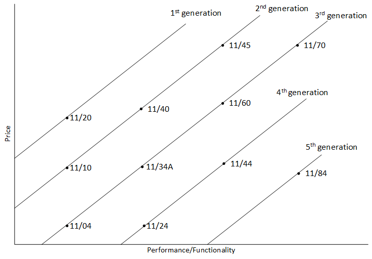
Figure 6 Performance/Functionality versus Price (#6 PDP-11 UNIBUS Processor Handbook pg 1-3)
At the Fire Department we used four members of the PDP-11 family, 1) 11/34, 2) 11/45, 3) 11/70, and 4) 11/84, although not all at the same time. This worked well because they all used the same instruction set and the assembler language Macro-11. For most of the life of Starfire we used the 11/70’s and the 11/34’s. The software for the 11/34’s was maintained and compiled on the 11/70’s. When eventually the 11/70’s were replaced by the 11/84’s, the 11/34 software was maintained on the 11/84.
The rationale for the agency to use the different family members is the ratio of cost to performance. This is the same rationale for DEC to create the different family members. By maintaining the same architecture across the family, we were able to select the appropriate servers for the desired function and keep costs down.
As you can see in the above diagram of price-versus-performance, the 11/84 is described to be of equal performance/functionality of the 11/70 at a lower price. This is a little misleading in that the price, in this case, includes purchase price. Taken separately, the maintenance cost of the 11/84 was much less than the 11/70 because the older parts were hard to come by. Also the performance was much better because peripherals such as the disk controller was much more sophisticated.
The switch from the 11/70 to the 11/84 did entail changes to the Starfire operating system. As I was the system programmer I had to make these changes. The Massbus was eliminated. On the 11/70 this was used for Direct-to-memory (DMA) transfers between devices such as the disk drives, tape drives, and some communication devices. To read from a disk drive, the disk controller was told what disk address and data size, what memory address. Then the controller would transfer the data and signal the CPU when the transfer was complete. Other devices would make data available on the device interface and the operating system would perform the transfer. The 11/84 used a more sophisticated disk drive controller which required changes to the operating system to support. Once that was done, however, the application programmers saw almost no difference.
2.3.13 - Hardware
2.3.13.1 - Tape Drives
Each system had two tape drives as part of the configuration. The tape drives are used to copy incident history information off of the live system for the purposes of creating daily incident reports. The tapes are created on the production system and read on the off-line system.
2.3.13.2 - Removeable Disk Drives
Originally Starfire used RP06 disk drives. These drives had a capacity of 176 MBytes. They contained the executable image for the operating system, the applications, and the system files.
2.3.13.3 - Fixed-Head Disk Drives
Originally Starfire hosted three RS04 Fixed-head disk drives. These drives had a capacity of 1 Mbyte each. They were designed as fixed-head to deliver very fast write and reading speeds. These devices were chosen to be the repository of the system checkpoints.
2.4 - Concentrators
When Starfire was designed, in the late 1970’s, the designers chose 9600 baud circuits to connect each of the borough dispatch offices to the central data center, which was located in lower Manhattan. There may have been circuits with higher data rates available, but the 9600 circuits were deemed sufficient. They actually configured three circuits for each borough. The data was transmitted synchronously, which gave the highest throughput possible on a circuit. The use of DDCMP, which is a transparent protocol, meant that numeric values did not have to be converted as ASCII before being put on the line. Still, this was not a very high volume to support the many devices that were present in each borough. Also, the design had the requirement of monitoring the status of each device so time wouldn’t be wasted attempting to communicate with a unit whose communications device was not working. So Bradford designed a local computer to handle the local monitoring load while distributing messages efficiently. This device was called a Concentrator.
The computer for the concentrator was a PDP-11/34. The system booted from a floppy drive. It had a console. It did not have a hard drive or printer. It did not store any operational information. The concentrator also did not use an operating system, such as RT-11. The software could be considered an Embedded application in that it was operating system and application in a single executable.
One of the ways the concentrator reduced traffic on the synchronous lines was to include a list of destinations at the head of a message that was destined for multiple devices. In that way, the messages was only transmitted by Starfire once assuming all the destinations were in the same borough. The concentrator would parse the destinations list and put the message on the right circuits for delivery. Dispatch tickets that went to multiple firehouse, often the case, was one situation that benefited Summary screen updates, which happened a minimum of every twenty seconds, and for any significant update, is the second situation that benefited.
The device used for all communications was the DV-11. The concentrator executable included the configuration and settings for every port. Upon boot-up, the concentrator set the port configuration then immediately began polling the devices. When Starfire booted up, or when a borough was transitioning from down to up, it was assumed that all devices were up and ready. When the concentrator began polling, if the device responded, nothing further would happen, but if three polls in a row were not acknowledged, the concentrator would send a Down status for that device to Starfire. The Concentrator would subsequently send to Starfire and change in the status of a local device.
There were two concentrators in each borough. There was also a device that connected the two concentrators to all devices. This device could be remotely controlled from Park Row, thus enabling remote switching between concentrators. The concentrator could also be remotely rebooted through a device that interrupted the power, thus causing a system restart. Finally, concentrator software could be remotely downloaded across phone circuits, so that updates did not require the a physical presence. Concentrator updates were always changes in device settings, new or deleted devices. The majority of these updates were changes to the deployment of fire units.
2.4.1 - Concentrator Client
While Starfire was designed before TCP/IP was commercially available, the concentrators did act like Clients, in that they established the connections to all asynchronous devices and began the polling activity. The connection to Starfire central system was a little different in that both ends of the synchronous connection began polling on the link as soon as initiation was complete. Each end marked the link up when it received a properly formatted poll from the other end.
2.5 - Sub-Systems
When the contract for Starfire was let, there were many legacy systems in place that had been designed for manual interaction by the dispatchers. The earliest telegraph-based alarm box system was implemented in 1871 (#23 Fire Alarm Telegraph Bureau, Bronx Central Office). This system made use of spring-loaded, coded wheels in each box that, when triggered, interrupted the circuit it was connected to in such a way that the box number was rung in the central office. If box 1256 was pulled, the dispatchers would hear the bells ring one time, followed by a pause, then two times, pause, five times, pause, and finally six times. This allowed the connection of many boxes on a single run of electrical cable. The newer Emergency Reporting System implementation, begun in 1968 (#25 Reducing Fire Engine Dispatching Delays), enabled voice communication between the caller and the dispatcher, and display the box number digitally at the call-taker’s console. As these system pre-dated the implementation of Starfire, special embedded computer system were designed and installed to provide an interface to Starfire, relieving Starfire from the requirement of interrogating each device. With the exception of the SRS, the purpose for creating specialized computers the interface with these systems was to reduce the amount of processing that the central computer had to perform and to localize the field communication manage tasks.
2.5.1 - Alarm Boxes
The Alarm Boxes are the original means through which the public could report a fire to the dispatchers.
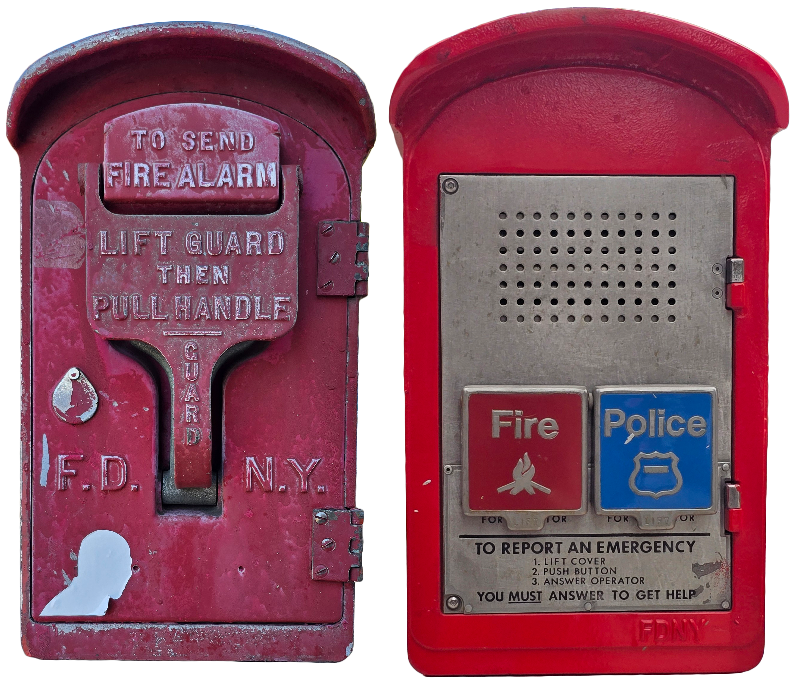
Figure 7 BARS and ERS Boxes (Kevin Jones)
2.5.1.1 - Box-Alarm System
Since the BARS system (Box-Alarm Readout System) (#24 Computerized Dispatching in Brooklyn) is a telegraph system, automatically entering the number of the activated box merely requires counting the circuit interruptions. The protocol included repeating the transmitted box a number of times so the dispatchers were ensured in being able to record the number. It also included a process for handling multiple boxes pulled on the same circuit. Bradford designed and built an embedded computer system, following the existing protocol, that transmitted the number to Starfire digitally. After the system was deemed reliable, the audio sounding of the bells in the central office was discontinued. A visual display was added and placed where the decision dispatcher and supervisor could see it. A paper copy of all received BARS alarms was also produced.
The BARS system allows a dispatcher to know that a member of the public has requested a response from the Fire Department. The inclusion of the box number means that the dispatcher also knows the location of the request. No other information is provided.
2.5.1.2 - Emergency Response System
The Emergency Response (or reporting) system is a much-improved communication system over the older BARS boxes. This is because the system allows the person making the request to inform the dispatcher the reason they are making the request. This is an essential refinement if the agency is to tailor the response to the need. Tailoring the response is essential when there is a high level of incident activity and there is a need to husband the firefighting resources in order to provide the best service. When a BARS box is pulled the department treats it as a structural fire and sends a full assignment, Three engines, Two Ladders, and a battalion Chief. But if the person who pressed the ERS button says they are reporting a rubbish fire, the dispatchers can assign a single engine, reserving the other units for other incidents.
As in the case of the BARS system, Norelco created an embedded computer that delivered a digital signal to Starfire when an ERS button was pressed.
2.5.2 - Status Reporting System
The Status Reporting System (SRS) was designed as part of the Starfire project to support continued operations on the dispatch platform when the computer system was not operational. There was little evidence that told what level of reliability the agency could expect. The requirements included creating a stand-alone computer in each borough that took input from a specialized keyboard, displaying the updated status locally on the “Chipboard”, and storing the updates when Starfire was down. Then when Starfire became available, the SRS could upload the status updates, effectively bridging the affects of the downtime. There were three devices on the platform connected to this system, 1) the Status Entry Panels (SEPs), 2) The Chipboard, and 3) The status map.
2.6 - Dispatch Floor Equipment
2.6.1 - CRT
The user interfaces for Starfire were custom designed and built for th project. As this was the early days of computer systems they were known simply as CRTs (Cathode Ray Tubes). I will refer to them as CRTs for the remainder of this document. In the mid 70’s when these were designed there were very few video terminals. Most of those that did exist were block-mode devices like the IBM 3270 (#21 Cruz, The IBM 3270). With block mode devices, a session begins with the computer transmitting the information defining a screen to the terminal, which displays the contents to the user. This screen includes the text and fields, and positions the cursor at the start of one of the fields. As the user enters individual keystrokes, they update the screen, including moving the cursor around the screen and deleting characters. These entries are not transmitted to the computer as they occur. When the user reaches a point that they are satisfied with their updates, the hit a “Submit” button. AT this point, the updated fields are transmitted back to the central computer. Simultaneously, the terminal keyboard is locked to prevent any further updates. Once the computer has received the transmitted data and confirms it’s validity, it either transmits a blank screen if appropriate, then it transmits a message unlocking the terminals keyboard. The Starfire CRT followed this same process. But the CRT included twelve “Hot Keys”, eight of which resulted in transmitting the screen contents back to Starfire. These are:
2. Defer
3. Release
4. Next
5. Cancel
6. Print
7. Page
8. Save
9. Display Queue
10 Notification
Whenever any of these buttons are pressed, the entire contents of the current screen along with an identifier that documents which button was pressed is transmitted back to Starfire. Even if there was nothing on the screen at the time, this was actually the IDLE screen which conformed to the standard for screen definition.
In the following photograph of Brooklyn Communications Office, the custom keyboard could be seen in front of the dispatcher. It is the dark blue device with the white and red keys. The red keys on the right are the “Hot” keys.
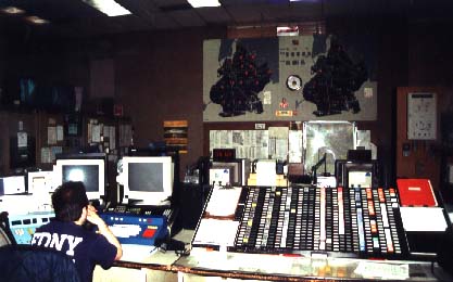
Figure 8 Brooklyn Decision Dispatcher Position (Britton Crosby)
Whenever any of these buttons are pressed, the entire contents of the current screen along with an identifier that documents which button was pressed is transmitted back to Starfire. Even if there was nothing on the screen at the time, this was actually the IDLE screen which conformed to the standard for screen definition. This form of communication was designed to keep the number and rate of input/output operations to a minimum, thus not overloading the available interfaces. Eventually, keystroke terminals such as the VT100 were produced, along with interfaces that supported them. These devices made for improved interaction with the user, which really came into prominence once data rates and capacities improved.
2.6.2 - Status Entry Panel (SEP)
The Status Entry Panel is a specialized keyboard for use in quickly entering incident and unit updates.

Figure 9 Brooklyn Radio Dispatcher Position (Britton Crosby)
The Status Entry Panel is a specialized keyboard for use in quickly entering incident and unit updates.
2.7 - Firehouse Equipment
2.7.1 - ATS
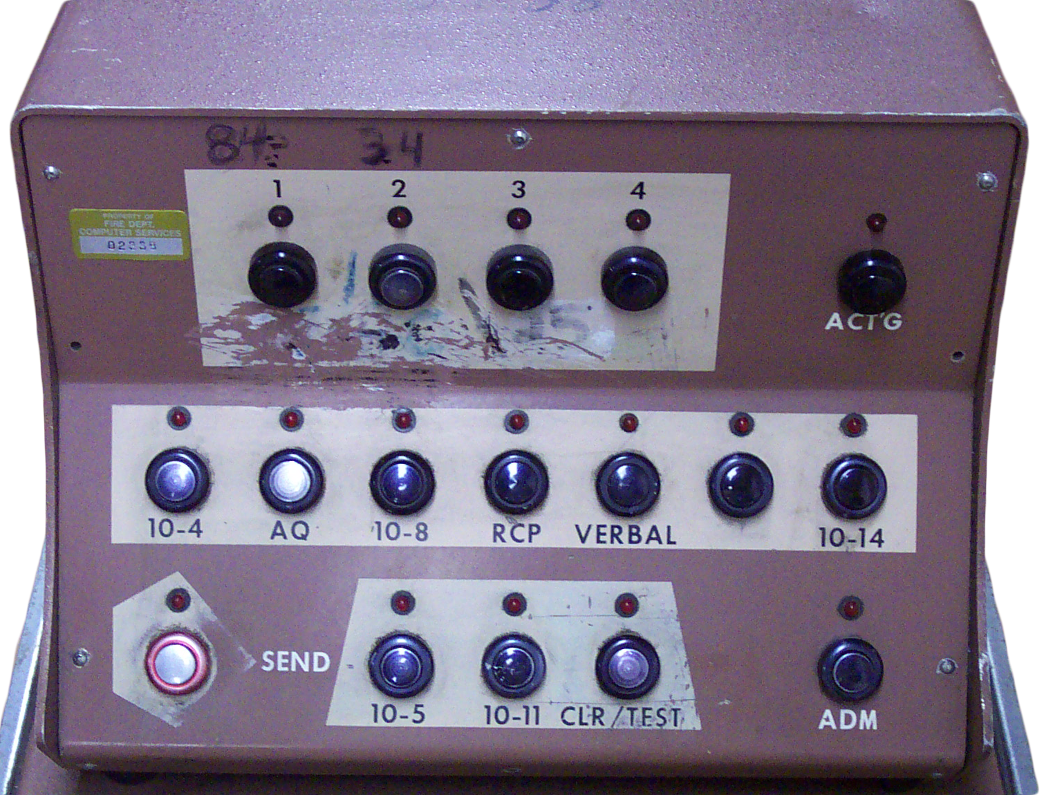
Figure 10 Alarm Teleprinter/Selector (Kevin Jones)
A device for the delivery of incident tickets and the receipt of unit status was designed and called the “Alarm/Teleprinter Selector”, or ATS. This consisted of two pieces of equipment in a stand. The input device contained buttons for the unit(s) to use to transmit acknowledgments and other unit statuses such as “returned to Quarters”. This device also contained the circuits to manage communications on the multi-drop current-loop cable that ran to the central office. These devices could be chained together on a single cable with a maximum of eight ATS per cable. The average number of devices per circuit was five. Each device was configured with a single-digit address (0-7) which was used for identification. Each device was polled by the borough concentrator. If there was an outbound message, the message was appended to the poll. The protocol allowed that multiple devices on the circuit could be addressed in the poll, such that a message that was common to more than one firehouse on the circuit would could be sent at one time. Inbound messages were only delivered after the device was polled with the question, “Do you have anything to send”.
In order to keep project costs down, existing circuits that had previously supported the old Bells system were reused to support the ATS. They converted the circuits to current-loop but had to boost the power to 60 milliamp from the usual 20. This also meant that the data rate could not be any higher than 300 Baud.
The ATS devices were installed in the Housewatch in each firehouse. This is the traditional room at the front of the firehouse were a firefighter was always on duty to man the communications with Dispatch and to announce any runs or other important information within the firehouse on the internal public announcement system.
In addition to a set of possible status, the ATS device also had four buttons used to identify which unit is to be associated with any inbound status button. If a dispatch ticket was received by the Engine, Ladder, and Battalion Chief in one house, the Housewatch firefighter would respond by hitting the 10-4 button, the Engine button, the Ladder button, and the Chief Button. The response would identify the four buttons in the message.
The process of delivering and receiving acknowledgments was as follows:
1. A dispatch ticket that is destined for three firehouses on a given circuit is put on the line by the concentrator. The preceding poll includes the three single-digit identifiers.
2. After the message has been completely transmitted, the concentrator requests the first device, if it has successfully received a valid message. Valid means all the protocol bytes were present as expected and the transmitted BCC was correctly compared against the calculated BCC.
3. The first device responds with an ACK, signifying the correct receipt of the message.
4. The concentrator requests the second device if it has correctly received the message.
5. The second device responds with ACK, acknowledging receipt of the message.
6. The concentrator request the third device if it had correctly received the message.
7. The third device responds with ACK, acknowledging receipt of the message.
8. Next, the concentrator will poll the three devices to see of there is any inbound message. In normal practice, after the fire company had read the dispatch ticket, they will press the 10-4, acknowledging that they have been dispatched, tear the dispatch ticket off of the printer, then proceed to begin their response. The acknowledgment will not be transmitted immediately upon the pressing of the buttons, but the device will wait for the concentrator to ask it if there are any inbound messages. In actuality, the protocol is probably still acknowledging the proper receipt of the outbound message as the firefighter is walking out of the Housewatch.
9. The concentrator requests the first device if it has any inbound messages to be delivered.
10. The first device responds by transmitting the 10-4 signal along with which unit was identified by the firefighter.
11. The concentrator requests the second device if it has any inbound messages to be delivered.
12. The second device responds by transmitting the 10-4 signal along with which unit was identified by the firefighter.
13. The concentrator requests the third device if it has any inbound messages to be delivered.
14. The third device responds by transmitting the 10-4 signal along with which unit was identified by the firefighter.
15. The concentrator then returns to the idle polling pattern.
The concentrator would forward each of the inbound messages to Starfire across the synchronous lines along with a device identifier so it was clear from which firehouse the message originated.
The second piece of equipment was the printer that was used for the incident tickets and other messages.
2.8 - Central Management Information System (CMICS)
The initial plan for Starfire was that it would run under the existing product, RSX-11D. However, early testing indicated that this would not deliver the required performance. The solution was to design and implement a custom operating system that supported the necessary devices and applications. This operating system was given the name CMICS.
The operating system consists of a number of source modules and tables that, when compiled and linked, form a memory image. The operating system is not an executable task in the standard sense, because an executable task is designed to operate in an environment provided by the operating system. The process of producing the operating system image uses the linker because that utility converts the object file into a file consisting of instructions, addresses, and offsets.
The PDP architecture expects certain values to be present at certain physical memory addresses and the image that is produced by the compile/link process must conform to that. For example, when a key is pressed on the system console, a trap is generated and the address and processor status word for handling this trap is picked up from 060/062. Thus the CMICS image must produce the correct address for the Console Interrupt Service Routine and place it at offset 060 in the image. Similarly, the image must use the address #17777566 when retrieving data from or writing to the console.
Some devices are not among the set that have fixed interrupt and device addresses, but are among those who are designed to use configurable interrupt and device address which cause them to be placed in the “Floating” areas. Once the hardware is configured, however, these values do not change and are likewise defined in the operating system source.
2.8.1 - CMICS Structure
2.8.1.1 - Structure
The layout of the operating system is dictated by the system architecture. For example, the trap address Console Terminal @ 060 expects to find the address of the routine for handling input from the console keyboard at that address. CMICS must conform to this expectation, define software to handle console keyboard and place the address of that routine at the expected memory location, or 060. When keyboard input arrives, the hardware interrupts whatever was executing, pushes the program counter and the processor status word onto the appropriate stack (Kernel, Supervisor, or User), and passes control to the defined address. The source code for CMICS defines an appropriate routine for every interrupt address, although if the associated device does not exist the routine may simply execute Return from Interrupt (RTI).
The maximum size of the operating system would depend on the number of available page address registers and the amount of memory each one could address. There were no facilities to modify the Kernal PARs. Of the eight available, the top one, PAR7, would be set to address high memory for accessing device interface registers. That leaves seven for addressing OS code. A Virtual Address used the three high bits to designate which PAR is being referenced. This leaves thirteen bits to address memory, or 2^13 = 8192 bytes. With seven PARs, each addressing 8192 bytes, the maximum kernal address space for code is 57,344 bytes. PARs 0 through 6 were set contiguously to address the low 57344 bytes of memory.
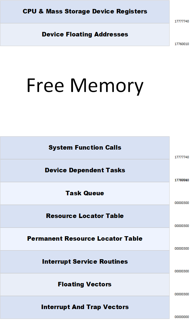
2.8.1.2 - Device Dependent Tasks
Device Dependent tasks (listed as DDT from here on) are supervisor mode routines that are dedicated to handling a specific device. They are written and compiled separate from the operating system image. They are loaded into memory by the operating system after it has taken over control. While it runs in supervisor mode, a DDT is still a module with a stack and references to resources as they are needed. When a DDT is not processing a request, it exists in a suspended state. A DDT can be interrupted like any other task when it necessary to do. DDTs, however, cannot be removed from memory. When a DDT is first loaded into memory it performs a small set of initiating instructions and without a request to process, it executes a “WAIT” instruction. This puts it in a suspended state where it will stay until a request requiring it’s response is submitted.
Generally a request that requires a DDT to respond can come from two areas. The first area is if an application makes a request. In the case of DSKDDT, the task that handles request to the disk, if an application submits a request to read a block from a file, the task will process the request and build the appropriate conditions for the read to take place, then issues the correct command to the disk. The DDT cannot access the device registers directly, but does so through the a call to the operating system. In the case of CMICS, this code was included in the Interrupt Service Routine. The ISR for the disks was named RPISR.
The second area is if the device signals a need for attention. For the PDP-11/70, the disk controller for the RP06 Drives was the MASSBUS controller, or RH70. The RH70 used Direct-Memory Access (DMA) for moving data between the device and memory, which means the ISR did not have to get involved in moving individual bytes or words. The controller signaled when a transfer completed. The signaling method was a trap to the appropriate vector address from where the address of the handling routine in RPISR. RPISR would respond by signaling DSKDDT which would awaken and complete the processing of the request.
2.8.1.3 - Resource Locator Table
The Resource Locater Table is used by the operating system to keep track of memory. With the exception of the OS Image, all memory is segmented into resources. All resources are memory resident. Each resource has a resource number that is used by an application to gain access to the resource. The resource locater is defined by a global address and a size. All system resources are identified by a resource number. The resource number always occupies offset 0 (zero) in the resource. The resource number is an index into the resource locater table. Each entry in the table is a 16-bit word that equals the block number of a 64 byte segment of memory. But the table did not contain enough entries to map every 64 byte chunk of memory. That would equal 65536 entries which would make the table larger than main memory. The largest a single block of memory could be was one memory page, or 8192 bytes. The number of entries required in the RLT assuming that every resource would be 8192 bytes is 512. But many resources were buffers used for inter-application messaging and would be 1024 to 2048 bytes. Most disk blocks were 512 bytes, so a buffer for reading and writing would be 576 or 1088 bytes in length. So probably the RLT contained around 2048 entries.
I do not remember how free memory was tracked. If a bit was used to designate each 64-byte block of memory as free or not, that resource would be 8192 bytes long. This would be a fairly simple process in order to find free memory when a request for a resource is submitted.
CMICS did have some utilities for recovering memory if it was beginning to run low. The read-only pages of user code, which are normally left in memory for efficiency, could be unloaded until they were needed later. I do not remember if there were routines to deal with fragmented memory.
2.8.1.3.1 - Permanent Resource Locator Table
The permanent resource locater table contains pointers to all permanent resources. The pointer is a two-byte page number. Permanent resources are identified by a number that is generated in the system source. The number is even and negative. The number translates the offset, from the global address of the resource locater table, and is negative. In this way, a permanent resource number is easily identified.
A permanent resource is one that is always in memory. Generally it is accessed by many modules but the only requirement is that it needs to always be in memory. The location of a permanent resource is not important because it is referenced through the locater table which always provides a means to know where it is.
2.8.1.3.2 - Temporary Resource Locator Table
The resource locater table contains pointers to all temporary resources. A temporary resource is created when a supervisor or user mode program makes a system call GETRSC. The system call includes the desired size of the resource and returns the resource number upon successful completion of the call. All resources are contiguous blocks of memory. When a temporary resource is no longer needed, it is returned to the free memory pool and removed from the RLT.
2.8.1.4 - Ready to Run List
The ready-to-run list is the ordered queue of tasks that have been requested to run and are not waiting for any resource. When an input from a dispatchers terminal is received, the task that is indicated to handle that input is built by TASKIT, creating a stack resource, and passing the resource number of the Task Parameter Block that contains the resource number of the resource containing the buffer transmitted by the dispatchers CRT. The resource number of the task, which is the resource number of the newly create stack resource, is placed in the last position on the ready-to-run list. Assuming there were other tasks already on the list, as they complete and are removed from the list, when the task that has been created to respond to this CRT input reaches the top, CMICS will transfer control to that task.
Should this new task make a disk read request, it will be removed from the ready-to-run list, placed in a queue of tasks waiting for a disk read to be completed, and other tasks on the RTL will be passed control. Once the requested disk read is completed, the requesting task is returned to the RTL, by placing the stack resource number back on the list, waiting for it’s return the top of the RTL.
2.8.2 - Resources
A resource is a section of memory. It is a minimum of 64 bytes and can be as large as 8192 bytes. Every resource contains in the first word, it’s resource number
2.8.2.1 - Temporary Resources
Temporary Resources are any resource that is used by a process until the task is complete, and then returned to available memory. The majority of all memory uses constitute a temporary resource. It is easier to give examples of permanent resources because the number of them is relatively small. But one temporary resource that may be a surprise is the memory used for code modules. It is true that code modules are not removed from memory simply because a process exits. In this case, the resource is retained since it is likely to be used again for another process. This keeps disk reads down. But there is processing that attempts to regain memory if available memory begins to fall below a desired limit. When this happens, memory used for code modules that are not currently being used can be returned to the free pool. It is this fact that means even code modules are temporary resources.
Then there are the obvious uses of memory;
2. Memory for screen buffers
3. Messages being sent to an MDT
4. Messages received from a borough concentrator
5. Text being sent to the console
6. Text being sent to the line printer
7. A command being sent to DHDDT to shut the MDT line down
These resources are obtained through the “GETMEM” macro. Each resource is assigned a resource number which is stored in the first word of the resource. The resource can be released using the “RELMEM” macro, or if the resource is still mapped when the process exits, it is automatically returned to the free pool.
2.8.2.2 - Permanent Resources
Permanent resources are those that reside in memory for the life of the system. They are designed to maintain information about the state of the system or the resource they are designed to track. One example of a permanent resource is the incident table, the resource that tracks open and recently closed incidents. If a task is instantiated to make an update to the incident table, that task requests access to the table, makes it’s update, then exits. The incident table remains in memory after the task ends, ready for the next task to request access. Permanent resources are never owned by a task although tasks are granted access for the duration of their access need. Permanent resources are identified by their resource number which is always negative. The name of a permanent resource always has the extension “.TAB”.
2.8.3 - Tasks
2.8.3.1 - Task Model
A task is an application. Another name for a task is process. It could be a supervisor or user mode application. All kernel mode software is part of the operating system image and thus does not exist as a task under CMICS. There are three parts to every task, 1) the code, 2) the stack, and 3) any resources permanent and/or temporary currently being addresses by the tasks. A task executable code is limited to one memory page, or 8192 bytes and is read-only. All task variables must be defined in the stack area and cannot exist within the address range of the code module. Actually, there is never more than one copy of a given code module in memory even though there could be multiple instances of the module on the ready to run list at any given time. Each instance would have it’s own stack containing the instance variables and the list of mapped resources.
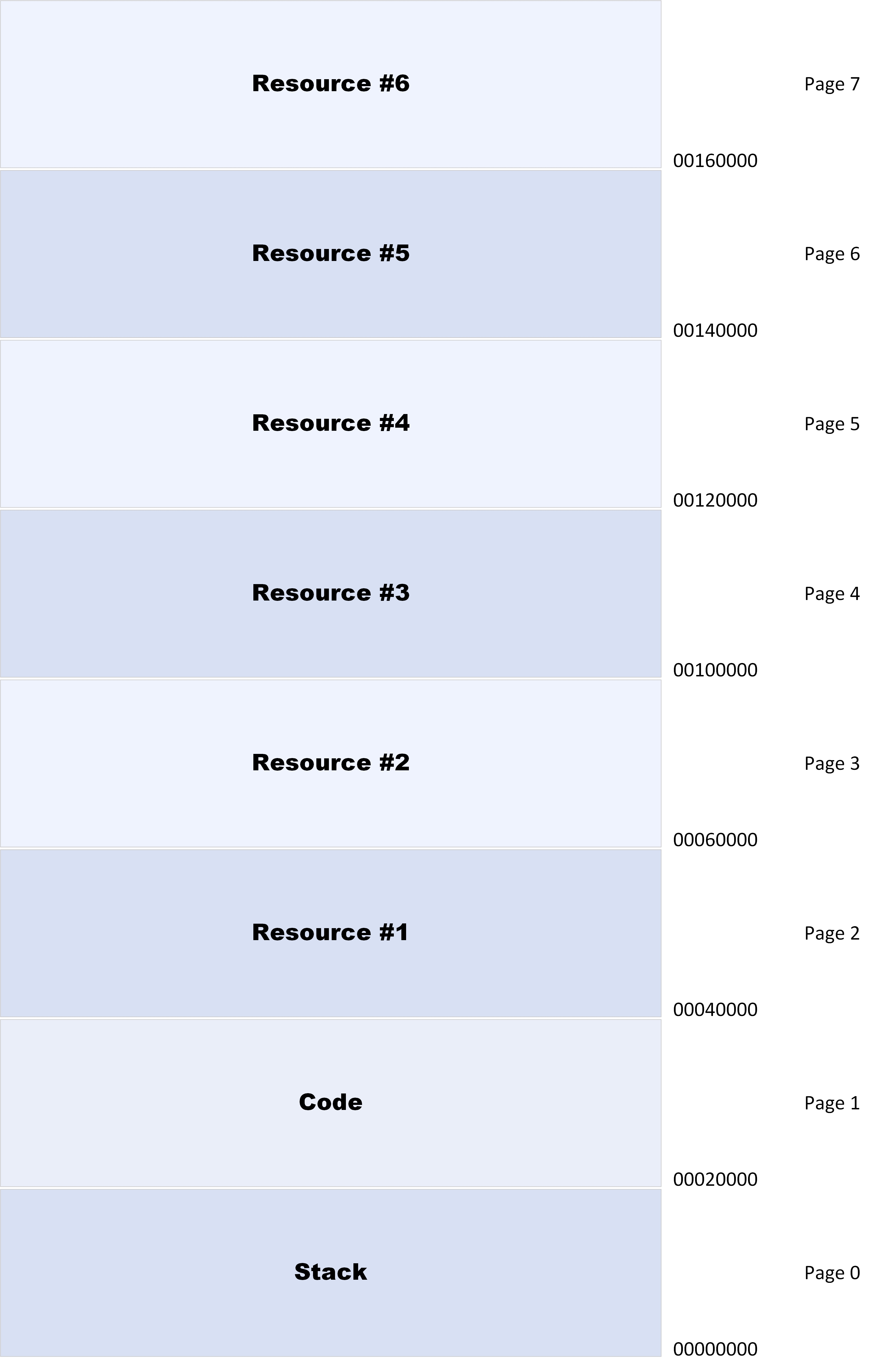
2.8.3.2 - Task Stack
The stack contains reserved space for storing the user registers and psw when the task is suspended. In this way everything that is needed to transfer execution back to the task is contained in the task resource. Since the code module is shared among multiple tasks, when it is loaded into memory from disk, it is left in memory after the tasks completes. This reduces the time it task to start another instance of the code module when it is needed. These resources can be recovered if available memory becomes low.
Below is an example of a typical stack definition. This defines 380 bytes of memory. The desired amount of space to be addressed by the stack pointer plus the space required to store the eight registers (including SP and PC), the page address registers, and the program status word (34 bytes), would be added to this, rounded up to the next 64-byte block, and made available to the task when it is created and loaded. Any combination that went beyond 8192 bytes would cause an abort when the task image was being created in the maintenance environment. Obviously, the stack pointer (SP) would initially point to the top of this resource and be decremented as items are pushed onto the stack. The value “WRKEND” would be used to check that the stack pointer does not cross into the area reserved for variables.
000 B0NAME = 0
002 TPNAME = B0NAME+2
004 BINBOR = TPNAME+2
006 BINCBO = BINBOR+2
008 ASCBOR = BINCBO+2
010 ASCCBO = ASCBOR+2
012 BINBOX = ASCCBO+2
014 AUNAME = BINBOX+2
016 ECBWRD = AUNAME+2
018 AANAME = ECBWRD+2
020 IDNAME = AANAME+2
022 ERRCNT = IDNAME+2
024 MODCNT = ERRCNT+2
026 WTOBUF = MODCNT+2
106 BOXNUM = WTOBUF+80
110 CBUF = BOXNUM+4
114 ENGPT = CBUF+4
156 LADPT = ENGPT+42
188 SUPT = LADPT+32
220 CHPT = SUPT+32
262 RE1PT = CHPT+42
328 RL1PT = RE1PT+66
364 TOP = RL1PT+36
368 BOT = TOP+4
372 IDX = BOT+4
376 ARRAY = IDX+4
380 WRKEND = ARRAY+4
2.8.3.3 - Task Code Module
The code module contains the actual instructions. It is read-only so any attempts to write into this address space would cause the application to be aborted.
2.8.3.4 - ReEntrancy
CMICS was designed to support modules that are reentrant (#8 Reentrant Function). A reentrant procedure is one that can support multiple processes, each with different specific content. This is essential for a multi-process system to be able to handle tasks in a timely manner. Reentrancy means that a task can be suspended at any point in it’s execution in order to service a higher priority task or switch to another process when the task must wait for an event to compete such as reading from disk. To be able to support reentrancy the module has no locations within the limits of the module that can be modified for any reason. All working locations must be external to the code module and be tracked as part of the process, including the address of the next instruction to be executed. All registers are saved when the process is suspended and restored prior to executing the next instruction. Starfire used a task parameter block to record this information. An example is the module “ADRBOX”, which handled the input for all twenty call takers when they were processing a call from the public. During a typical Friday evening or any working fire, the number of simultaneous calls can easily saturate all available call takers. Each call required retrieving reference information from disk or transmitting screen information across the network. Each of these calls present a situation that cause the suspension of a given transaction opening a window to process one of the other outstanding transactions. In such a case, the process being suspended would be put into a waiting state by copying all registers, page-address registers, program counter, program status word, current stack pointer, and the identities of any temporary memory resources, followed by restoring these same resources from a formerly suspended process into the user mode registers and transferring control to the new program counter location. To ensure this works each time one of the restrictions on the application is that no variables are stored within the code space, which wouldn’t be copied or restored as part of the swapping process. In fact, the Starfire architecture dictated that all variables are stored on the processor’s stack. All other variables either exist in temporary memory resources or permanent memory resources. As long as these restrictions are followed, a given process can be swapped in and out many multiples of times before completion without error. Another advantage of reentrancy is that a given code module need be written into memory only once. Each running process would contain it’s own stack and temporary memory, but once a module, for instance “ADRBOX” is in memory, any subsequent invocation of this module will use the already existing instance of the module. In order to force this architecture, each code module is written into memory as a read-only resource. This eliminates the possibility that a module would attempt to write data into the code space.
2.8.3.5 - Task Creation
When a task is to be created, the name of the associated code module is provided to “TASKIT”. A memory resource is requested to hold the stack area. “LOADER” is called, which first checks to see if the code module is already loaded into memory. If not, a resource is requested and the executable image is read from disk into the resource. LOADER returns the resource number of the code module to TASKIT.
This is where the advantage of Reentrancy is leveraged. Since the code module stores no values related to a process, there need only be one copy of the module in memory no matter how many processes exist at a time referencing that module. Any differences are expressed in the copy of the module stack.
Once the code module is available, either the process is put on the ready-run-list, or control is passed to it to begin executing. The difference is base on how the task was initiated. If it was initiated by another process using the “LINK” or “XCTL” (transfer control) macro, then the new module is essentially a continuation of the calling modules process. If, however, the new module was initiated using a “SCHD” (Schedule), macro, the new module will be treated as a completely new process, and will begin executing at a point in the future.
The calling task will have created a “Task Parameter Block”, which will contain any and all relevant information pertaining to the reason a task was initiated, details of expected processing, and the resource numbers of resources needed to complete the processing.
2.8.3.6 - Task Termination
When a task has reached it’s processing end, it will exit. What happens next depends on how the task was initiated. If the task was initiated though the “LINK” macro, control will return to the calling task. If it was initiated through the “XCTL” macro, there is no calling task. If it was initiated through the “SCHD” macro, also, there is no calling task. In all three of these cases, the task stack is returned to free memory. The code module remain in memory for use in future invocations.
2.8.3.7 - Inter-task Communication
All inter-task communication is handled through the creation and passing of Task Parameter Blocks as part of a LINK, XTCL, or SCHD macro invocation. Another way to communicate with other tasks is to create a TPD and place it on one of the functional queues (see Functional Queues).
2.8.4 - Booting
When Starfire was being started up, the command that started the process was executed under RSX. This main task of this process was to take control of the system away from RSX, so it has to be linked with the appropriate privilege such that RSX would relinquish control. It then built up an image that included enough of the operating system and copied that image into low memory, overwriting RSX.
This image included the code that would process any and all device interrupts. The devices that interfaced with the PDP-11 were all interrupt driven devices. Each one was configured with an interrupt address, and a location in memory through which the device could be addressed. The interrupt address is the address that the program counter would be loaded with when control was being passed to the interface to satisfy the interrupt. The appropriate code must be in place before interrupts could be enabled for a given interface. This routines, known as Interrupt Service Routines (ISR) were part of that minimum OS image.
During this time essentially there was not a fully capable operating system in memory, so interrupts had to be disabled, which was something that only an “Executive Mode” process could do. After the partial image was loaded into low memory, control was passed to that image. Once control was passed to the CMICS image, RSX was no longer in control even though not all of RSX has been replaced. The first task for CMICS after control had been passed was to load the remainder of the operating system into memory.
2.8.5 - Programmed Interrupt Requests
A Programmed Interrupt Request is a software trap. There is a trap request that the operating system responds to but it includes a request number that further designates what action is to be taken.
2.8.6 - File System
One of the casualties of the decision to implement a custom operating system was the need to limit some of the functionality that is normally expected from a computer system. The RSX file structure was a mature implementation that included all the file handling functions we expect today; Create, Read, Update, and Delete. In order to improve performance, and perhaps reduce the additional burden of the decision to write a custom operating system, CMICS did not include the ability to create a file, delete a file, or extend a file. It was also limited to block mode binary files, no text files were part of the system. Instead, a limited, separate file table was created, that was populated during the off-line maintenance session. Starfire could only read and update. Also, designating a file for access was done using a file number, access using a file name do not exist.
2.8.7 - Maintenance and Development Environment
While Starfire ran under the CMICS environment, the maintenance tasks were initialy executed under the RSX-11D environment. The operating system was designed to support primarily batch processes and was limited to single user interaction. During the time that FDNY used RSX-11D, the only maintenance peripherals were the console, a line printer, disk drives, tape drives, and a IBM card reader. Changes to the software modules were implemented through the card reader.
Eventually RSX-11D was replaced by RSX-11M+ which included support for multiple simultaneous users and video terminals such as the VT100. With the VT100 came the editor “EDT” and productivity for the software team soared.
Source code control was implemented through a binder that used a red front and back, and thus was called the “Red Book”. Even though the red book was eventually replaced by a more traditional log book, the essential format of recording source code changes remained the same until Starfire was finally retired in the summer of 2021.
There was no way to execute the Starfire modules under RSX, so debugging source code edits required bringing up a test version of the system. Also, there were no printers that could be controlled directly by a given module so debugging routines were created that would send messages and dumps of data to the peripherals that were available to help in the debugging process.
2.8.8 - Utilities
2.8.8.1 - System Dump
When Starfire was delivered to the Department, it did not include a way to capture the details of an aborted system other than what was printed on the line printer. This meant that we had to leave the system down while the dump printed or restore dispatch operations quickly. Also, reviewing the dump using only the printed version was time consuming. One of the early improvements our team performed was to modify the operating system to write the system dump to disk, then automatically restart and return functionality to the dispatchers.
A system dump did still represent a serious fault, but in most cases the system was able to return “Warm” meaning that all open incidents were still open, all unit statuses were still accurate, and the dispatchers could resume from the point the system crashed. In a small percentage of cases, the system dump was caused by an incident-related fault, meaning that that incident might not be in a working state. But most often the fault was caused by a communications fault that was unrelated to an operational message.
Once the dump was available on disk, reviewing it became much faster, and I could write tools to help. I give more details on this later in the document.
2.8.8.2 - Application Dump
When a user application aborted, it would not impact the system itself, and dispatch operations could continue unaffected. The event that was being handled by that process could possibly be affected in that it was not handled to completion. When Starfire was delivered, an application abort was sent to the line printer. The dump would include the task stack, the code module, and any resources mapped at the time of the abort. If a task abort was printing when another abort happened, the system would abort. Busting the dump required reading the printed dump.
We implemented the writing of the task abort to disk. This reduced the likelihood of a system dump because of multiple application aborts. It also meant that reading the dump was much easier. We eventually created a system screen that allowed a quick review of the dump, and only printed it if we needed to. In many cases, we could understand the reason for the abort just through review on the screen. The project to implement this facility is detailed later in this document.
2.9 - Checkpoints
When Starfire was first implemented the disk drives were too slow to support all the live activity while writing and reading all information from disk. All the important tables were designed to the memory-resident with historical records of events written to disk. While a user could recall the historical records from disk, most of the instantaneous information was kept in the memory-resident tables. In order that this information could be retained on case of a system restart, updates to these tables were written to the checkpoint disks. Checkpoints are running records of system activity and support two levels of system restart when necessary. There are actually three levels of restart:
The first level; initial, restarts the system with no incident history and all units available in quarters. This is the level that is used when there are no checkpoints available, or if it is desired for some reason. If initial restart is selected with checkpoints available, they are ignored.
The second level of restart; cold, retains the historical record of incidents that have occurred, but any incident that was open at the time of the restart will be marked closed with no units assigned and all units will be available and in quarters. History refers to the record of historical fire activity, the units that were assigned, and all other events in chronological order.
The third level of restart, warm, retains the historical record of all incidents, both open and closed, all unit statuses and their incident assignments. If the system is restarted warm, the dispatchers would experience a short interruption in availability, but when the system was available again they could continue, largely, where they were interrupted. Messages in queues were also check-pointed and restored on a warm start.
A checkpoint is written when one of the designated memory tables is updated. It is not the update that is written, but the entire entry that was updated is copied to the checkpoint after the update is applied. This made for a simpler restore process despite resulting in a larger initial write. Also, at certain intervals, the entire table is written to the checkpoint.
An example of this process is the updating of the Incident Table (ITN where N equals the borough number). When a new incident is opened in Brooklyn, an empty entry in IT4 is found and information about the new entry is written into that entry. At the same time, the next record in the round-robin disk file for Brooklyn, CI4 is determined from the history tracking numbers also found in IT4, and the CI tracking number for the current day is updated. Immediately, both the new incident entry in it’s entirety and the updated tracking pointers are written to the checkpoint file.
In the case of a “Cold” start, after the fresh IT4 table is copied from disk, the incident tracking numbers and their associated day code are retrieved from the checkpoint file and the data is applied to the table in memory. No further updates are made to IT4 from checkpoints because a “Cold” start is limited.
In the case of a “Warm” start, in addition to the activities in a “Cold” start, each of the individual incident entries (A maximum of 96 per borough) that are not designated as “Free”, are copied from the checkpoint file and applied to the appropriate table entry. Beyond the “IT” tables, when a “Warm” start is selected, all other tables that contain recent incident or unit related information are restored from the checkpoint files. Device status information is not check-pointed as devices are constantly polled and their status is re-established upon restart.
2.10 - Software
2.10.1 - MACRO-11
MACRO-11 was the assembler language used for all PDP-11 systems. DEC offered other languages but FDNY stuck with assembler, even through to the the migration to Vaxes and Integrity family of computers. A “C” compiler became available but was used by FDNY only in the development environment. Actually, the compiler first converted all “C” into assembler then used the DEC compilers there after. When DEC released the 11/84, they added some new instructions to MACRO-11. The basics of this assembly language is the instruction set that existed on the PDP-11 family of computers. It included, however, a powerful feature, given the functional name “MACRO”. A macro includes a set of instructions that, at compile time and prior to the creation of the object file, expand to create multiple instructions, manipulating variable names, using rules that may be conditional. This is an important feature of the language.
2.10.1.1 - Macros
A Macro is a hugely important aspect of the MACRO-11 Language. It is not a PDP-11 instruction like “MOVB” is. A Macro’s greatest value comes in it’s expansion during the compilers first pass into actual PDP-11 instructions. Following is an example of the use of the macro “GETMEM” to obtain a block of memory. The example shows calculating the necessary length of memory needed followed by initiating the resource.
MOVW #INP,R5 ;address input buffer
MOVW #20,R1 ;20 bytes for unit name
ADDW2 #150,R1 ;add length for header
ADDW2 MNNSL(R5),R1 ;add string length
GETMEM #TKT,R1,TKTNAM ;get memory for message
MOVW #TKT,R0 ;address output buffer
1$: ;;;;
CLRB (R0)+ ;clear buffer
SOB R1,1$ ;
The first four instructions determine the length of the string to be transmitted. The first parameter of the macro call states which base the resource should be mapped into. TKT was earlier defined as BASE5, which equates to octal 120000. The second field contains the required amount of memory, The third field states where the resource number should be stored. “TKTNAM” is defined as a location on the modules stack. The next three instructions zero out the memory. The actual memory returned would be rounded up to the 64-byte boundary.
During the compilers first pass, the macro would be expanded to the actual instructions that would include pushing each of the parameters onto the stack, followed by issuing a TRAP instruction. The operating system would define a Trap routine for this function, say “TRAP 12”. The macro would call the appropriate Trap, relieving the developer from having to remember which was the appropriate one. The macro would also perform some basic parameter validation. At compile time, the macro would ensure that three parameters were defined. Errors at this point would result in compiler errors. At run time, the macro could check that the length of the request was greater than zero and less than or equal to the maximum of 8192. Errors in this case would result in an application abort with a abort number to specify the nature of the error.
I well designed and implemented macro saves the developer a lot of time, makes the code easier to read, and enforces many enterprise standards.
Following is a sample macro definition. This is a for requesting a read from the disk. It has four parameters. The expanded macro pushes the four parameters onto the stack then issues the appropriate trap instruction. When control is returned to the application, the status word is placed in R0, and the stack pointer is returned to the position it held at the beginning of the macro call.
.MACRO DISKREAD BASE,FILENO,BLKNUM,BLKCNT
MOV BASE,-(SP)
MOV #FILENO,-(SP)
MOV #BLKNUM,-(SP)
MOV #BLKCNT,-(SP)
TRAP 04
MOV (SP)+,R0
ADD #6,SP
.ENDM
2.10.2 - RSX-11
2.10.2.1 - RSX 11/D
RSX-11D was the operating system available for commercial use on PDP’s when the Starfire project was first begun in 1976. This operating system provided all the essential utilities required for writing, compiling, and building the software for Starfire. It supported Files-11, the RP06 disk drives, and TU16 Tape drives. It also supported memory management. The original plan for Starfire was that the software would run under this operating system. This was a single user system and did not support user accounts nor require logging in to the system. The only input terminal was the system console. There were line editors that were available for maintaining source code. Bradford included a CR-11 Card Reader which was the preferred method for code maintenance.
2.10.2.2 - RSX 11/M+
RSX-11M was first released in 1979. The letter “M” denoted that this included user accounts and could support multiple users simultaneously. It also supported video terminals and we got our first VT100s when we upgraded to 11M Plus. We installed DH-11’s to support the VT100s. Nothing about the maintenance of starfire software changed, meaning that MACRO-11, Compiling, and Building utilities stayed the same. Being able to user EDT in Screen editing mode, however, was like going from a Model-T to a Mustang GTO! This change had no impact on Starfire itself, since which ever operating system was used for maintenance was written over at system boot time.
2.10.2.3 - Maintaining source code
2.10.2.3.1 - Compiling objects
All applications were written in MACRO-11. With the infrastructure that supported it, it was a very powerful language. Of course, it was created specifically for the PDP-11 family of computers. Every computer in the family could run applications written in MACRO-11 although the applications may have required the use of a linker written for the OS. The command “MAC” was used to compile a source module (with extension “.mac”) and create an object (with extension “.obj”). The object file was not created if there were any fatal compile errors. The compiler would list errors on the console or terminal, but if the option to create a listing was included, all errors were also included there. The standard line printers in those days were 165 columns in width, so the listing was formatted for that width. The standard listing was very informative and there were many compile options dedicated to formatting the listing file.
The listing would include the actual instruction opcode on the same line as the textual instruction. These values could be compared to the descriptions included in the processor handbook. This was an essential data point when it came to busting system and application dumps. The listing would also include the physical address of all instructions and labels.
The compiler is a two-pass compiler (#17 MACRO-11 Language Reference pg 1-2). During the first pass, all macros are expanded to their derived instructions or data values. Only after this expansion could correct addresses and offsets be determined. Then in the second pass the actual opcode and data values were created and written into the object file. The compiler would flag errors such as attempting to branch to a label further away than could be included in the 8 bits (+256 to -254 bytes) alloted for it (#4 PDP-11/70 Processor Handbook pg 4-38).
The designers were able to leverage the object files for use in Starfire and CMICS through use of the existing command line options and arguments. No special processing was required.
2.10.2.3.2 - Building Application executables
Following the compiling of a source module or modules, the next step would be to create the executable image. The RSX utility for this step was “Task Builder” (#19 Task Builder Manual). For the simple applications, the build included a single object file as source and a single executable as destination. Since these tasks were not destined to run in a RSX environment, the standard task headers were not needed and excluded through command line arguments. None of the executables contained any read-write areas, so this was specified in the command line arguments. All executables were limited to one memory page in length, or 8192 bytes. None, with one exception, included any execute code or mapped the I/O page. The one exception to these rules is the CMICS loader, the program that loaded CMICS into memory and transferred control of the computer to CMICS.
Symbol Tables were an essential aspect of maintaining Starfire applications and tables. A symbol table includes global symbols defined in one source, the symbol name and value. The symbol table allows one independently compiled source to correctly reference symbols defined in another independently compiled source at run time. Bradford established standards and practices for managing global symbols across the application.
2.10.2.3.3 - Building CMICS
CMICS is the name of the operating system itself. It is not an executable that runs under any other operating system. It does, however, consist of executable code modules and data sections. One very important data section is the area of low memory that corresponds to the interrupt and trap vectors. The values that exist in this space are addresses of the modules to which control is passed when an interrupt occurs and the value of the program status word that is used. For instance, the source module for the system clock Interrupt Service Routine, KWISR, is maintained as an independent source module. The label for the starting address of this module is calculated as the offset, from zero, to the location of the label. In the data section that defines location 100 (octal) the label for KWISR is located in the module source followed by the program status word that should be used.
CMICS also contained some read-write areas. One example is the Temporary and Permanent resource locater tables. In the source, these are empty tables but there bounds are defined. During the startup process, as resources are loaded or built, the resource numbers are added to the table. There would also be queue heads for the Ready-to-run list. As much as possible, fixed memory resources in the operating system are kept to a minimum. Queues headers for disk transactions would exist in the stack for DSKDDT, which would be derived from a temporary resource.
The command for building CMICS would exclude any task header. It would also include many object files, which combined together would create the CMICS Image. I use the term “Image”, because, even though we used Task Builder to create it, it was not a task or executable that runs under an operating system. The process of building the CMICS image used an indirect file. The reason is the large number of input object files, symbol tables, and the importance in their listed order.
2.10.2.3.4 - Building CMICS Loader
CMICS Loader was responsible for loading CMICS into memory and subsequently moving it into position starting at physical zero. This task ran under RSX. It’s normal operation required it to violate all the rules put in place to stop a program from interfering in the smooth operation of the operating system. It had to have the priority necessary to get past the operating system’s defenses. Luckily, DEC provided the options necessary such that CMICS loader could do what was necessary. Bradford didn’t have to engineer some special function or hack for this to work. The build options were available and documented.
This task did not use RSX memory management. It’s functionality was fairly simple. It loaded the OS image into memory, addressed low memory, copied the OS image, performed some initial setup, then transferred control to CMICS itself to execute the balance of the setup tasks.
2.10.2.4 - Booting the System
After all the system components have been prepared, the first step in starting the system was booting it into memory and transferring control to the operating system. An application that was not part of CMICS was written to perform this task. This application was compiled with the necessary privileges such that it could overwrite RSX. Applications without such privilege would be aborted by RSX if it tried to write in system spaces.
The first step was to read the CMICS executable image into memory. The boot application was actually named “CMICS.EXE”, to make it easy to remember the command to start the system. But as this is also the name of the operating system, I will refer to the boot application as CMICSBoot for clarity. CMICSBoot was able to use RSX provided services to address the executable file on disk. Using the appropriate symbol table, the CMICSBoot knew the exact size of the executable through the appropriate symbol table. The application also used RSX services to request the necessary amount of memory to contain the executable. The CMICS executable image was then copied into the requested memory. This is the last action that used RSX services.
The next step was to copy the executable image into low memory, starting at memory address zero. It is for this reason that CMICSBoot had to be compiled with the appropriate privilege. Once the executable had been copied into low memory, free memory was processed and listed as such. I do not remember exactly how free memory was tracked, although I can think of more than one method.
CMICSBoot did not load all the initial tasks into memory, but queued up application load requests to be executed by CMICS once it had control. The Device-Dependant tasks would be the first applications loaded. And while they could be loaded by CMICS, the DDT for the disk drive would be necessary for CMICS to carry out these tasks. For this reason I believe the boot application loaded all the DDTs into memory, then placed them on the ready-to-run list starting with DSKDDT. This would have been after CMICS was moved into place and prior to transferring control to CMICS. The trap vectors for all devices were compiled as part of the CMICS executable image, and thus, were put in place when the image was copied to low memory. Starfire used a number of memory-resident tables. They were memory resident for performance purposes. These tables are used to track the many incident and unit statuses, information about the status of the borough concentrators, the link to the MDT system, and the workflow queues. Finally, CMICSBoot would transfer control to CMICS which would complete the boot process by converting the memory containing CMCSBoot to free memory and begin selecting tasks from the ready-to-run list to execute.
Each of the DDTs were responsible for initializing their respective device before going into a wait state. DSKDDT, did not need to set up any resources at this time as didn’t have to respond to unsolicited events. It would set the appropriate values into the device registers in high memory. Of course DSKDDT did not address high memory directly, but made the calls to RPISR, which was allowed to address these registers, to set the values. After initialization, the module would go into a WAIT state, ready to respond to any disk requests.
DVDDT, the task for managing the DV-11, had a lot of setup to perform. First it had to set the write configuration for each port. There were sixteen in all, three for each of the five boroughs, and the last one for Central. The mode (Synchronous or Asynchronous), BAUD rates, character size and parity for each port had to be set. Then, since the device would be responding to unsolicited input, and since this is a DMA device, a memory resource had to be requested, with it’s memory address given to the device for each port. All these activities would be performed during the initialization phase, but handled through calls to DVISR. Then the device was initialized. This was done by setting the INIT bit. This was not a synchronous activity where the system waited for the Device Ready bit to be set, but it was an Asynchronous activity where the setting of the Device Ready bit was communicated through the device trap. The remaining DDTs would similarly be executed as they became the top task on the ready-to-run list, and after performing their initialization would enter a wait state.
The next tasks will be the loader to loads all the system tables into memory. Following that will be the tasks the bring up the boroughs. Actually, Starfire does not bring up the boroughs because Starfire waits for the borough concentrator to attempt to bring itself up by contacting Starfire. So Starfire will will mark the borough ready to come up so that when it receives the borough restart message from the concentrator, Starfire can respond appropriately.
2.10.3 - DDCMP
The Digital Data Communications Message Protocol is a reliable data communications path between devices connected by communications links (#29 DDCMP Message Protocol). DDCMP ensures correct message sequencing and error-free data transmission.
2.10.4 - Peripherals
There were five peripheral devices connected to the central Starfire computer. Three were DMA (Direct Memory Access) that were serviced through the MASSBUS RH70 controller (#26 RH70 Special Massbus Controller). The other two were supported through programmed I/O.
2.10.4.1 - RP06
The RP06 was a multi-platter, removable disk-pack drive. Each pack had a capacity of 176 MBytes. The data transfer rate was 806 KBytes/Sec. Typical PC hard drives of today, while delivering capacities much larger than this also offer transfer rates more than 300 times as fast (#27 Western Digital Blue). But for the time this system was implemented and with the understanding of the limitations, Bradford was able to design the files and file access such that the performance needs of the system were met.
The interrupt address was 2548 and the device register address was (177767008 - 177767528) (#4 PDP-11/70 Processor Handbook pg A-2, A-6)
2.10.4.2 - RS04
The RS04 was a fixed, single platter device that provided faster response over that of the RP06. Both sides of the platter were used. The data transfer rate was 21% faster, but the real advantage was the 375% improvement in access time (#2 RS04 Disk Drive). The Starfire configuration included four of these drives. These drives were used for purposes that required frequent writing and reading. The two functions were 1) Checkpoints, and 2) Queues.
Check-pointing was the act of recording updates such that the system could be restarted while retaining the current incident and unit status information. This was known as a “Warm” restart. If the system restarted warm, all incidents that were open at the time would still be open with the correct set of units assigned. The status of all units would be retained across the restart.
The message and work-flow queues were essential to the management of all incidents. Queues were modified for the majority of incident and unit status events.
The interrupt address was 2048 and the device register address was (177720408 - 177720728) (#4 PDP-11/70 Processor Handbook pg A-1, A-8,A-9)
2.10.4.3 - LA36
The LA36 was the system console. It contained a keyboard and it’s output was a dot-matrix print-head on 165-column fan-fold computer paper. It was the device through which the system was started and halted. This device did not have a controller on the UNIBUS, but was addressed specifically through it’s own trap vectors (608/648) and device addresses (177775608 - 177775668) (#4 PDP-11/70 Processor Handbook pg A-1, A-4).
2.10.4.4 - TU56
There were two tape drives on each computer. These tape drives were connected through the RH70 Massbus controller. While Starfire was operational, the tape drives were used to transfer daily incident history from the system to the off-line system for printing reports. The command to initiate writing a day’s history was entered on the system console.
The interrupt address was 2248 and the device register address was (177724408 - 177724768) (#4 PDP-11/70 Processor Handbook pg A-1, A-7,A-8)
2.10.4.5 - LP-11
The LP11 was the system printer. This device had a controller on the UNIBUS, and was addressed specifically through it’s own trap vectors (2008) and device addresses (177775148 - 177775168) (#4 PDP-11/70 Processor Handbook pg A-1, A-4). In the production environment, the line printer was used for printing system and application dumps and incident histories. There was no print queue in CMICS, so an attempt to print a history while one was printing would not be serviced.
2.10.5 - Devices
2.10.5.1 - DV-11
The DV-11 was used for communication between the central system and the concentrators (#18 DV11 Communications Multiplexer). It natively supported DDCMP and BiSync. It automatically calculated a 16-bit polynomial BCC, embedded the BCC in the message being transmitted, and checked it upon receipt. For long messages, there were multiple BCCs embedded. No CPU cycles were required for these activities. The DV-11 used the RH70 Massbus controller for connections to memory and was a DMA (Direct Memory Access) device.
The DV-11 was also used for the asynchoronous communications with the user workstations, the sub-systems such as ERS, BARS, SRS, and the line cards that supported the 60 mil current loops to the firehouse.
2.10.5.2 - KW-11
The KW-11 was the system programmable clock (#5 KW11-P Clock Manual). It provided the means to create timed events for the application. The device could be programmed to interrupt continuously at a determined interval and to execute a single interrupt at a defined interval. The Macro “SCHED” allowed a task to be initiated XXX milliseconds from the time the macro was executed. This would use the one-time interrupt. The continuous interrupt at a determined interval was used to mark the passage of time. Tasks could be initiated every minute. The summary screens were refreshed every few minutes even if there had been no change to the displayed incidents or units. Also, messages were sent out to the firehouses at every shift change
This device did not have a controller on the UNIBUS, but was addressed specifically through it’s own trap vectors (1048) and device addresses (177725408 - 177725468) (#4 PDP-11/70 Processor Handbook pg A-1, A-7).
2.10.5.3 - DH-11
The DH-11 was a 16-line Asynchronous Multiplexor (#28 DH-11 Asynchronous Multiplexor). In the off-line environment it was used to connect the VT100s to RSX-11M+ for user sessions. In the production environment it was used to connect Starfire to the PRC Message-switch for Mobile Data Terminal communication. This was eventually expanded to communication with the EMSCAD and NYPD Sprint systems for the Certified First Responder project.
The DH-11 was a programmed I/O device. This meant that every byte of data that was either received or transmitted was moved between the device and memory through CPU instructions. These instructions were part of the Interrupt Service Routine, DHISR.
This device would have been installed with an interrupt address (see Table 3 Floating Interrupt Vectors and Table 4 Floating Addresses)
2.10.6 - CMICS
2.10.6.1 - Data Sections
A Data section is a description of data that exists in memory. It provides the means for an application to know where to find a value that it requires to perform an operation. When done properly, the conventions around how data is described help the develop to identify where to find data, and in what format (bit, byte, word, long word, string, etc) the data is stored. In Starfire, data sections were used to define every variable and data resource in the system. Some aspects of the operating system contain important addresses whose addresses never change while the system is running. In these cases the addresses are absolute, meaning the value resolves to an absolute address in memory and does not require an intervening pointer. One such resource is low memory where system traps reside. Another resource is high memory where interface device registers reside. These values are compiled in such a way as to create a full 22-bit address (Base plus Address). These absolute data sections are only compiled as part of the operating system executable as this is the only code whose location in memory is know at compile and link time.
All other data sections are created with the assumption that the memory it is defining can be located at locations that cannot be assumed at compile and link time. Even for those modules that would not be moved around in memory after the system is started, the location it may be initially installed into could change if a module that is normally loaded beforehand may grow in size through software modifications resulting in a different starting position when the system is restarted. For the majority of applications, they get moved around in memory over time. A module that is loaded to a certain location may eventually be unloaded when there is a need for memory, and when it is required again is reloaded into a different location.
For this reason, most data sections are defined with the address of the first variable in the section set to zero. All subsequent addresses increase above the initial zero, depending on the size of each variable. If the value located at location zero is a word, then the offset of the next value, regardless of it’s type, will be two.
The Starfire practice was to use the first two letters to name a resource. There are a small number that used three initial letters, especially when there are two or more that were related, such as “BF0”, “BF1”, “BF2”, and “BF3”. For the data section the next three letters would be “DSP”. Starfire used the first two letters of a resource name to identify that resource. Thus the data section for a block in the Alarm Assignment file would begin with “AA”. Within AADSP, the data section for the Alarm Assignment File, the two first letters of each field are also AA.
Starfire included a number of permanent memory resources used for tracking resources such as units, incidents, and street locations. Following is a portion of the Street file data section:
;--- intersection street ---
ITEM SNIBA,20 ;basic name
ITEM SNIPR,3 ;prefix
ITEM SNIEN,4 ;ending
ITEM SNISF,5 ;suffix
The following sample code from “ADRBOX”:
SN = BASE6
MOVW #<SN+SNHDRL>,R1
TSTB SNIBA(R1)
The first line defines the base address for the Street Records, which is 140000 Octal. The length of the block header is 52 (SNHDRL), thus the combined value is 140064 (Octal). The second line loads this value, the offset to the first street records in the block, into R1. The third line (second instruction) tests the first byte of the first street entry in the block. Once R1 has the offset to the first street entry, the developer can use the defined offset for each field in the resource in this way.
Actually, the correct definition of “Register Indirect” would be the instruction TSTB (R1). This is actually a valid way of testing the first byte because the record offset SNIBA actually equals 0 (zero). The example listed above is actually “Displacement addressing” which is a combination of direct addressing and register indirect addressing.
2.10.6.1.1 - AADSP
;;;;;;;;;;;;;;;;;;;;;;;;;;;;;;;;;;;;;;;;;;;;;;;;;;;;;;;;;;;;;;;;;
; LOOKUP ID DATE INITIALS COMMENTS
; --------- -------- -------- --------
;;;;;;;;;;;;;;;;;;;;;;;;;;;;;;;;;;;;;;;;;;;;;;;;;;;;;;;;;;;;;;;;;
.title AADSP AA file record definition
.macro AADSP, gbl
.MCALL RECDEF,ITEM,ORG,OCCURS,ENDOCC,ENDDEF,EQUMAC
EQUMAC
.LIST ME
RECDEF AA, gbl
ITEM AABOX,4 ;box number - ascii
ITEM AABX2,2 ;box number - binary
ITEM AALIT,130 ;location literal
ITEM AAXXX,2 ;x coordinate
ITEM AAYYY,2 ;y coordinate
ITEM AAADM,4 ;admin company
ITEM AAPCT,4 ;police precinct
ITEM AANB1,4 ;near box 1
ITEM AANB2,4 ;near box 2
ITEM AANB3,4 ;near box 3
ITEM AANB4,4 ;near box 4
ITEM AADAY,2,D ;julian date as required
ITEM AADIS,2,O ;pointer to special
;dispatch instructions
ITEM AAFL1,2 ;flag 1 - special response policy
ITEM AADRB,,A,DB ;discretionary response box
;(no bc needed)
;may also have 2 bytes - #eng + #lad
ITEM AAFL2,1 ;flag 2 - mandatory dispatch value
ITEM AAMANL,,A,1 ;mandatory ladders
ITEM AAMANE,,A,2 ;mandatory engines
ITEM AAMANB,,A,3 ;mandatory both
ITEM AAFL3,1 ;flag 3 - box type
ITEM AADUMM,,A,D ;dummy box
ITEM AAERS,,A,E ;ers
ITEM AASING,,A,S ;single action bars
ITEM AADOUB,,A,G ;double action bars
ITEM AACL3E,,A,R ;class-3/ers
ITEM AACL3M,,A,M ;class-3/manual
ITEM AACL3D,,A,F ;class-3/dummy
ITEM AASOL,,A,O ;Solar
ITEM AACL3S,,A,L ;class-3/Solar
ITEM AAPOI,2 ;pointer to read this record
;(fill when reading)
AAHDRL == DISP$ ;length of header
OCCURS AALIN,5 ;one line of aa card occurs 5 times
ITEM AAEN1,2,O ;eng 1
ITEM AAEN2,2,O ;eng 2
ITEM AAEN3,2,O ;eng 3
ITEM AAEN4,2,O ;eng 4
ITEM AALD1,2,O ;lad 1
ITEM AALD2,2,O ;lad 2
ITEM AALD3,2,O ;lad 3
ITEM AASP1,2,O ;special unit 1
ITEM AACH1,2,O ;chf 1
ITEM AACH2,2,O ;chf 2
ENDOCC AALIN
OCCURS AASPU,5 ;special units for five lines
ITEM AASP2,2,O ;special unit 2
ITEM AASP3,2,O ;special unit 3
ENDOCC AASPU
OCCURS AACCU,5 ;covering chiefs for five lines
ITEM AACC1,2,O ;covering chief 1
;second covering chief is null for
;lines 4 and 5
ITEM AACC2,2,O ;covering chief 2
ENDOCC AACCU
OCCURS AARLP,4 ;relocation pairs
ITEM AAR11,2,O ;relocating unit 1
ITEM AAR12,2,O ;reloc into unit 1
ITEM AAR21,2,O ;relocating unit 2
ITEM AAR22,2,O ;reloc into unit 2
ITEM AAR31,2,O ;relocating unit 3
ITEM AAR32,2,O ;reloc into unit 3
ITEM AAR41,2,O ;relocating unit 4
ITEM AAR42,2,O ;reloc into unit 4
ITEM AAR51,2,O ;relocating unit 5
ITEM AAR52,2,O ;reloc into unit 5
ITEM AAR61,2,O ;relocating unit 6
ITEM AAR62,2,O ;reloc into unit 6
ENDOCC AARLP
ENDDEF AA
.ENDM AADSP
2.10.6.1.2 - ITDSP
;;;;;;;;;;;;;;;;;;;;;;;;;;;;;;;;;;;;;;;;;;;;;;;;;;;;;;;;;;;;;;;;;
;
; LOOKUP ID DATE INITIALS COMMENTS
; --------- -------- -------- --------
;;;;;;;;;;;;;;;;;;;;;;;;;;;;;;;;;;;;;;;;;;;;;;;;;;;;;;;;;;;;;;;;;
.TITLE ITDSP Incident table
.MACRO ITDSP
.MCALL EQUMAC
EQUMAC
RECDEF IT
;
; incident table
;
; header
;
ITEM ITLEN,2,O ;total length inclusive of resource
ITEM ITOCC,2,D ;maximum entries in table
ITEM ITHHH,2,D ;header length
ITEM ITEEE,2,D ;length of 1 entry
ITEM ITTOD,2,D ;todays julian date - ddd
ITEM ITTK1,2,O ;last tracking number used today
ITEM ITTK2,2,O ;last tracking number used yesterday
ITEM ITTK3,2,O ;last tracking number used 2 days ago
ITEM ITTK4,2,O ;last tracking number used 3 days ago
ITEM ITTK5,2,O ;last tracking number used 4 days ago
ITEM ITTK6,2,O ;last tracking number used 5 days ago
;tracking number index is null if -1
ITEM ITCIM,2,D ;maximum ci tracking numbers
ITEM ITDY1,1,D ;day code for today
ITEM ITDY2,1,D ;day code for yesterday
ITEM ITDY3,1,D ;day code for 2 days ago
ITEM ITDY4,1,D ;day code for 3 days ago
ITEM ITDY5,1,D ;day code for 4 days ago
ITEM ITECT,1,D ;incident entry enqueue count
ITEM ITEIT,2,O ;task id enqueueing entire table
ITEM ITEWT,2,D ;wait time for any incident enqueue
ITEM ITHFL,1,O ;header flags
ITBODN = 1 ;boro down
ITMAJR = 2 ;major update occurred, need sumcrt
; now
ITSMNO = 4 ;restart suppress summary updates
ITEM ITHCT,1,O ;count of higher alarms
ITEM ITBOR,1,A ;borough character
ITEM ITBON,1,O ;borough numeric code
ITEM ITOVR,2,O ;resource number of overflow area
ITEM ITFIL,2,O ;filler
;
; incident entry
;
OCCURS ITENT,96
ITEM ITACT,1,O ;active flag
ITFREE = 0 ;free area is null
ITACTV = 1 ;open incident
ITDUMM = 2 ;dummy incident used to hold space for
;ers first round
ITCLOS = 3 ;closed incident
ITDUMS = 4 ;special dummy for sumcrt to hold work
; spacein this incident table for
; x-boro references
ITDUME = 5 ;special dummy for newecp
ITEM ITDAY,1,D ;day code
ITEM ITTRK,2,O ;ci tracking number
ITEM ITBOX,2,D ;box number
ITEM ITSUF,1,D ;suffix number
ITEM ITDDR,1,D ;dd reason code
ORG ITDDR ;redefine dd reason code for ci file use
ITEM CICLR,1,D ;close reason
CIXNOR = 1 ;close normally
CIXMFA = 2 ;close for false alarm
CIXNSO = 3 ;close for nso
CIXHAR = 4 ;close for harassment
CIXECP = 5 ;close for ecp
CIXDWN = 6 ;closed by restart after system down
CIXNAR = 7 ;closed for no action required
CICFRH = 8 ;closed for CFRH
ITEM ITRCD,4,O ;time alarm received
ITEM ITSC1,1,D ;source of alarm
ITBARS = 1 ;bars
ITFON = 2 ;phone
ITVERB = 3 ;all verbal alarms
ITCL3 = 4 ;class-3 box
ITERNC = 5 ;ers no contact
ITERS = 6 ;ers
ITSRS = 7 ;srs report
ITEMS = 8 ;ems
ITPD = 9 ;pd opened ems incident
ITEM ITSC2,1,D ;source modifier
ITERSC = 1 ;ers consoles are busy (ers-w)
ITERST = 2 ;ers has timed-out
ITRADV = 3 ;radioed verbal alarms
ITERT0 = 4 ;ers-t with timeout = 0
ITEM ITAAP,2,O ;pointer to aa rec
ITEM ITLET,1,A ;letter code (1-5, a-s,t)
ITLSTR = ^A/1/ ;structural
ITLNST = ^A/2/ ;non-structural
ITLRST = ^A/3/ ;recent still (historical)
ITLOST = ^A/4/ ;old still
ITLCPL = ^A/5/ ;complaint
ITLMDW = ^A/E/ ;multiple dwell a
ITLBSH = ^A/N/ ;brush
ITLRBS = ^A/O/ ;rubbish
ITLTRN = ^A/P/ ;transportation
ITLEMG = ^A/R/ ;emergency
ITLMFA = ^A/S/ ;false alarm
ITLTRA = ^A/T/ ;transit
ITLMEM = ^A/V/ ;med. emergency
ITEM ITLEV,1,D ;alarm level
ITLEV0 = 0 ;complaints & stills
ITLEV1 = 1 ;first alarm
ITLEV2 = 2 ;second alarm
ITLEV3 = 3 ;third alarm
ITLEV4 = 4 ;fourth alarm
ITLEV5 = 5 ;fifth alarm
ITEM ITTEN,1,D ;ten code
ITEM ITCOD,1,D ;condition code
ITCOD1 = 1 ;code 1
ITCOD2 = 2 ;code 2
ITCOD3 = 3 ;code 3
ITCOD4 = 4 ;code 4
ITCOD5 = 5 ;code 5
ITEM ITFL2,1,O ;additional flag bits
ITHZ = 1 ;aids information for house on fire
ITHZ2 = 2 ;aids information for neighboring
; house
ITHZOF = 4 ;overflow in hazard table
ITIDS = 8 ;flag for initial dispatch (grant
; 10-14 once)
ITMDT = 16 ;closed by mdt
ITDUP = 32 ;flag for second ard screen
ITADD = 64 ;flag for additional information for
; the inc.
ITDSTC = 128 ;flag for disposition ten code
ITEM ITLFG,1,O ;itlit flag (how good is itlit)
ITONAA = 0 ;itlit just as read from aa
ITALSS = 1 ;itlit has st1 + st2 from al screen
ITALHS = 2 ;itlit has hou + st1 from al screen
ITI1SS = 3 ;itlit has st1 + st2 from incu screen
ITI1HS = 4 ;itlit has hou + st1 from incu screen
ITEM ITLIT,40,A ;box location or ecp name
ITEM ITXXX,2,O ;x coordinate
ITEM ITYYY,2,O ;y coordinate
ITEM ITPUL,4,O ;time last bars pulled or ers round received
ITEM ITDTM,4,O ;time entered in dd queue
ORG ITDTM ;redefine time of dd for close
ITEM ITCTM,4,O ;time of incident close
ITEM ITIID,2,O ;incident id (task id of 1st pgm)
ITEM ITFLG,2,O ;flag bits
ITWRKG = 1 ;working
ITSERI = 2 ;serious
ITRECM = 4 ;incd passed thru ddrecm once
ITICHG = 8 ;incd data changed since last sumcrt
ITUCHG = 16 ;unit data changed since last sumcrt
ITBLNK = 32 ;need to blink 'dd' on summary
ITMORE = 64 ;aalit has more than 60 bytes long
ITLCHG = 128 ;change was made to house,st1 or st2
ITREST = 256 ;incident restarted from either -1
; version on alternate or from
; essential information during
; system restart
ITSSPN = 512 ;suspended incident after boro down
; for one minute
IT1076 = 1024 ;10-76 has been entered for incident
IT1084 = 2048 ;10-84 has been entered for incident
ITICH2 = 4096 ;copy of itichg for sumuni
ITUCH2 = 8192 ;copy of ituchg for sumuni
IT1080 = 16384 ;10-80 has been entered for incident
IT1045 = 32768 ;10-45 has been entered for incident
ITEM ITTSK,2,O ;enqueueing task id
ITEM ITUNT,2,O ;address of first unit in incident chain
ITEM ITUCT,1,D ;count of current units
ITEM ITQFL,1,O ;queue for first alarm
ITQAR = ^A/A/ ;alarm receipt
ITQDD = ^A/D/ ;decision dispatcher
ITQVC = ^A/V/ ;voice
ITQRO = ^A/R/ ;radio
ORG ITTSK ;for restart redefine
ITEM ITUTM,6,O ;time of last update
ORG
ENDOCC ITENT
ENDDEF IT
.ENDM ITDSP
2.10.6.1.3 - SNDSP
.title SNDSP SN record
;;;;;;;;;;;;;;;;;;;;;;;;;;;;;;;;;;;;;;;;;;;;;;;;;;;;;;;;;;;;;;;;;
; MODIFICATION HISTORY
; 1. Lookup id will be used for searching code changes
; 2. All unwanted code should be COMMENTED NOT DELETED
;;;;;;;;;;;;;;;;;;;;;;;;;;;;;;;;;;;;;;;;;;;;;;;;;;;;;;;;;;;;;;;;;
;
; LOOKUP ID DATE INITIALS COMMENTS
; --------- ---- -------- --------
;;;;;;;;;;;;;;;;;;;;;;;;;;;;;;;;;;;;;;;;;;;;;;;;;;;;;;;;;;;;;;;;;
.macro SNDSP,gbl
.MCALL EQUMAC
EQUMAC
.LIST ME
RECDEF SN,gbl
ITEM SNHDR,52 ;header portion of file
ORG SNHDR ;redefinition of header
;--- header ---------------------------------------------
ITEM SNNAM,2 ;file name code 'sn'
ITEM SNBRO,2 ;boro code 'b '
ITEM SNFNU,2 ;file number(b=binary)
ITEM SNCNT,2 ;count of entries(bin)
;--- main street -----------
ITEM SNMBA,20 ;basic name
ITEM SNMPR,3 ;prefix
ITEM SNMEN,4 ;ending
ITEM SNMSF,5 ;suffix
ITEM SNFG1,2 ;flag(values follow)
ITEM SNLST,,O,1 ;last record for the street
ITEM SNLOH,,O,2 ;Low odd hyphenated
ITEM SNLEH,,O,4 ;Low even hyphenated
ITEM SNHOH,,O,10 ;High odd hyphenated
ITEM SNHEH,,O,20 ;High even hyphenated
ITEM SNNEF,,O,40 ;New file format
ITEM SNNAH,,O,100 ;All houses hyphenated
ITEM SNNHU,,O,200 ;Hyphenated and Unhyphenated
ITEM SNSOH,,O,400 ;Street lowodd hyphenated
ITEM SNSEH,,O,1000 ;Street loweven hyphenated
ITEM SNSNH,,O,2000 ;Street high number hyphenated
ITEM SNDLN,,O,4000 ;Discard number to left of hyphen
ITEM SNDRN,,O,10000 ;Discard number to right of hyphen
ITEM SNHAO,4 ;high-odd-address on record(bin)
ITEM SNHAE,4 ;high-even-address on record(bin)
ITEM SNROO,2 ;pointer to root of binary tree(bin)
ORG
;--- one entry ------------------------------------------
OCCURS SNENT,20 ;repeated structure of entries
ITEM SNLOD,4 ;low-odd-address on block
ITEM SNLEV,4 ;low-even-address on block
ITEM SNINT,32 ;intersection street name
ORG SNINT
;--- intersection street ---
ITEM SNIBA,20 ;basic name
ITEM SNIPR,3 ;prefix
ITEM SNIEN,4 ;ending
ITEM SNISF,5 ;suffix
ORG
ITEM SNBIN,4 ;pointers in binary tree
ORG SNBIN
ITEM SNLOW,2 ;low pointer
ITEM SNHIG,2 ;high pointer
ORG
ITEM SNBOX,2 ;box(bin)
ITEM SNBOR,1 ;box's boro (values follow)
ITEM SNBCM,,O,1 ;manhattan
ITEM SNBCX,,O,2 ;bronx
ITEM SNBCR,,O,3 ;staten island
ITEM SNBCB,,O,4 ;brooklyn
ITEM SNBCQ,,O,5 ;queens
ITEM SNFG2,1 ;box flag (values follow)
ITEM SNCOR,,O,1 ;box at corner of intersection
ITEM SNUSH,,O,2 ;u-shaped street - identical intersection
;exists later in this street record
ITEM SNCOH,,O,4 ;Odd Hyphen
ITEM SNCEH,,O,10 ;Even Hyphen
ENDOCC SNENT
ITEM SNSLO,4 ;STREET LOW ODD ;2.5
ITEM SNSLE,4 ;STREET LOW EVEN ;2.5
ITEM SNSHN,4 ;STREET HIGH NUMBER ;2.5
ORG SNBRO ;DEFINITION FOR HEADER BLOCK
ITEM SNVER,4 ;FILE VERSION
ITEM SNDBC,10 ;DATABASE CREATE DATE
ITEM SNFNC,10 ;FILE CREATE DATE
ORG ;
ENDDEF SN
.endm sndsp
sndsp gbl
.END
2.10.6.2 - Interrupt Service Routine Modules
Each of the following Interrupt Service Requests are the modules designed to support their specific device. All have two things in common, 1) respond to the instances when the device is granted a trap by the processor, and 2) respond to the instances when the request initiated through software requires interaction with the device control registers.
Instances in the first case are configured by the address of the appropriate source instruction is placed in memory at the interrupt address designated for the device in question. The next word contains the value of the Program Status Word to go along with the Program Counter. Some devices are supported by more than one interrupt addresses, for instance the Console (LA36) has an interrupt address pair for receiving characters and one pair for transmission completion.
Instances in the second case, following the above example, occur when software is transmitting text to the console. System software will issue either a TRAP or Programmed Interrupt Request which would be initiated by the appropriate Device Dependent Task.
2.10.6.2.1 - DVISR
DVISR is the Interrupt Service Routine for the DV-11. It is compiled as part of the operating system source code. The routine works hand-in-hand with DVDDT.
2.10.6.2.2 - RPISR
RPISR is the Interrupt Service Routine for the RP06 Disk Drives. It is compiled as part of the operating system source code. The routine works hand-in-hand with DSKDDT.
2.10.6.2.3 - RSISR
RPISR is the Interrupt Service Routine for the RS04 Disk Drives. It is compiled as part of the operating system source code. The routine works hand-in-hand with DSKDDT.
2.10.6.2.4 - DHISR
DHISR is the Interrupt Service Routine for the DH-11. It is compiled as part of the operating system source code. The routine works hand-in-hand with DHDDT.
2.10.6.2.5 - LPISR
LPISR is the Interrupt Service Routine for the LP-11 Line Printer. It is compiled as part of the operating system source code. The routine works hand-in-hand with LPDDT.
2.10.6.2.6 - KWISR
KWISR is the Interrupt Service Routine for the KW11-P Programmable Clock. It is compiled as part of the operating system source code. The routine works hand-in-hand with KWDDT.
2.10.6.3 - Device Dependent Task
One of the important distinction about communications between a DDT and the user-mode programs that interact with it is that the these interactions are asynchronous. When a user-mode program requests an activity, control is returned to the requesting program upon receipt and validation of the request. The requesting program may enter a wait state, but that simply means that the next process on the ready-to-run list is invoked. A request to write a block to disk might take seconds to be completed, while thousands of other events could be processed during that time. The user-mode program requesting the write can continue processing if such processing does not depend on the successful disk write.
2.10.6.3.1 - KWDDT
KWDDT is the Device Dependent Task for the KW11-P Programmable Clock. It is a supervisor mode program and is loaded during system startup process. Once the module is loaded, it is placed on the ready-to-run list and it executes it initiating process, followed by entering a wait-for-event state. The routine works hand-in-hand with KWISR.
2.10.6.3.2 - DSKDDT
DSKDDT is the Device Dependent Task for the RP06 and RS04 disk drives. It is a supervisor mode program and is loaded during system startup process. Once the modules are loaded, they are placed on the ready-to-run list and it executes it initiating process, followed by entering a wait-for-event state. The routine works hand-in-hand with RPISR and RSISR.
2.10.6.3.3 - DHDDT
DHDDT is the Device Dependent Task for the DH-11. It is a supervisor mode program and is loaded during system startup process. Once the module is loaded, it is placed on the ready-to-run list and it executes it initiating process, followed by entering a wait-for-event state. The routine works hand-in-hand with DHISR.
2.10.6.3.4 - DVDDT
DVDDT is the Device Dependent Task for the DV-11. It is a supervisor mode program and is loaded during system startup process. Once the module is loaded, it is placed on the ready-to-run list and it executes it initiating process, followed by entering a wait-for-event state. The routine works hand-in-hand with DVISR.
2.10.6.3.5 - LPDDT
LPDDT is the Device Dependent Task for the LP-11 Line Printer. It is a supervisor mode program and is loaded during system startup process. Once the module is loaded, it is placed on the ready-to-run list and it executes it initiating process, followed by entering a wait-for-event state. The routine works hand-in-hand with LPISR.
2.10.6.4 - File Table
When the decision to create the customized CMICS operating system was taken, part of the decision included how much of the existing commercial product would be included in the final product. One major aspect of this is how files are identified and accessed. The project was originally intended to run under RSX-11D which used Files-11/ODS-1 for file management. The ODS-1 implementation of Files-11 included all the standard file management capabilities such as 1) Read, 2) Write, 3) Extend, and 4) Delete. It also support file formats such as 1) Fixed Length records and 2) Variable Length Records.
The project team was faced with implementing partially or completely an interface to the Files-11 Master File Directory. The team decision was NOT to implement Files-11, instead, creating a separate file tracking resource, including only the minimal functionality necessary to stand up the application.
The implementation used a separate file table that is populated with the starting block number of each file and the number of blocks. This file table did not include any information about file ownership which was not used by Starfire. Due to the simplicity of the information contained in the file table, certain file management features were not available to Starfire.
The dominant factor is that all the files were binary data files. There were no “Text” files. Even though system files included text strings, they were all stored in fixed-length fields. The next big factor was that there was no ability to extend a file. Finally, since a file was defined only by starting block and count of blocks, all files had to be contiguous. Files-11 provided the ability force a file to be contiguous which was part of the system preparation process.
Some Starfire files were updated during normal operation. The file table was not integral to the process of updating a file and not information about the update was written into the file table. While many files were read-only, there was no file-based protections to prevent writing to one of these files.
Operationally, the inability to extend a file meant that writing to a file had to be managed so that writing did not write outside the bounds of the file. This fell into two modes, 1) The exact location of the update within the file was determined as a function of the update. For example, update block #17 in the Manhattan cross reference file, 2) adding records to the incident file for the Bronx requires determining that next block, designated by a tracking number and writing to that block unless at the end of the file which means writing to the first block in a round-robin fashion.
2.10.6.5 - Permanent Resource
A permanent resource is a memory-resident resource that is loaded at system startup and never removed. They served as memory resources that could store information that needed to be updated and referenced often and quickly, and would be relevant over a large period of time, hours and/or days. The borough specific incident tables, which are used to keep information about all open incidents are good examples of a permanent resource. These resources are not written to disk during the time that the system is running, but some portions of some resources are copied to the checkpoint disk when they are updated. These portions are restored from the checkpoint disk during a “Cold” or “Warm” restart as needed. For Instance, each borough incident table contains a record number the delineates the first and last incident record in the borough incident file. This is how the incidents for one day are segregated from the incidents for another day in the round-robin incident file. When the record numbers are updated in the incident table, the appropriate portion of that table is copied to the checkpoint disk. These values are restored from checkpoint for both a “COLD” and “WARM” restart.
2.10.6.5.1 - System Table
The System table is a permanent resource. It would contain information that did not warrant a dedicated memory resource, but maybe was used by many application modules. Below is a partial list of data elements that are maintained in the System Table.
1. System Startup / Shutdown Progress
2. Which CPU (CPU A / CPU B)
3. Borough Startup/Shutdown Progress
4. Borough Operational Status
5. Enqueue TaskID for Line Printer
6. Enqueue TaskID for Tape Drive
7. Alarm Rate Table for All Boroughs
8. Terminal Name for UNISYS Summary
9. Command Table
10. Screen Table
2.10.6.6 - Queues
Queues are the infrastructure by which multiple messages and events can be delivered for servicing in a manageable way. Generally queues on Starfire are designed to handle items in the order they are created, or First-in / First-out. Every user terminal (CRT), except the summary screen, has a queue associated with it. Starfire queues use a very simple means of tracking the items, the Queue Head, when empty contains zero, otherwise it contains the resource number of the first item on the queue. The queue head also contains the count of items on the queue. When there are more than a single item on the queue, the first queue item contains a forward pointer consisting of the resource number of the next item on the queue. The final item contains a zero for the next queue item. Every firehouse ATS and the Status Reporting Systems also have queues.
2.10.6.6.1 - Functional Queues
An essential aspect of Starfire is it’s use of functional queues to process dispatch tasks. The modern description of this is “Workflow”. Each functional queue is associated with one or more members of the dispatch floor staff and it is the means to deliver the appropriate task to the appropriate person.
Each queue is a logical collection of tasks, represented by a task-parameter-block containing all the information necessary for completing the task. The dispatcher who is assigned to process items from a given queue is automatically alerted any time a new item is placed on a queue to which they are assigned. Any person associated with a queue can retrieve items from the top of the queue by requesting the “NEXT” item, or they can examine the contents of their queues and retrieve an item, even if out-of-order. Generally, each queue is first-in, first-out (FIFO), although there eventually came cases where more sophisticated item retrieval was implemented. There is also a queue associated with every physical interactive terminal. This allows a TPB to be queued to a particular position, which is what happens when an ERS alarm is received and delivered to an available call-takers position.
The function queues are:
- Alarm Receipt (ARD)
- Decision Dispatcher (DD)
- Radio (RO)
- Voice Alarm (VO)
- Notification (NTF)
- Supervisor (SP)
The path for a typical alarm that has been received through the ERS system is as follows:
1. A member of the public presses an ERS button in the Street. A Task-Parameter-Block is created and populated with the information of the ERS Box Number and the location of the BOX. This TPB is queued to the position that the audio from the street box has been delivered to.
2. When the TPB is queued, the call-taker is signaled (Visually through the presentation of a red-background on the screen, and through the sounding of the PCs bell). This signaling is the only way events are delivered to a call-taker. Nothing is ever displayed automatically, but only after the person hits “Next” or retrieves an item from their queue(s). In this case, the phone is also ringing to indicate the arrival of a call.
3. The call-taker hits their “NEXT” button to retrieve the item from the queue. Starfire retrieves the TPB and uses it to build an alarm screen with the ERS box number and the box location. This screen is displayed to the call taker.
4. When the call-taker has completed the processing of the call, they will send the incident to the next stage by hitting the “Release” button. This causes the creation of a TPB, using the information from the alarm screen, which is added to the “DD” queue.
5. The DD will be signaled (as before) that a new item has been added to their queue. The DD hits the “NEXT” button to retrieve the item.
6. Once the “NEXT” button is hit, Starfire will retrieve the item from the top of the queue and use it to build the appropriate screen. In this case, the appropriate screen may be a “Dispatch Recommendation” or a “Potential Duplicate” screen. The building of the screen only occurs when the “NEXT” button is hit assuring that the screen is built using the most recent information. The screen is displayed to the DD. An incident could potentially be a duplicate when the call-taker completed processing the call. But during the time the TPB was in the DD’s queue, the incident that was potentially a duplicate has closed. Thus the new screen is delivered as a dispatch recommendation because it is no longer potentially a duplicate of the one that just closed.
7. After reviewing the screen, and potentially making some edits to the recommendation. The DD will press the “Release” screen, thus completing the dispatch recommendation. Depending on the status of the units assigned, a number of TPB’s are built and queued.
7a. If any of the assigned units were On-The-Air without working MDT’s, a TPB is immediately placed on the Radio Dispatcher Queue.
7b. If any units were in Quarters without working ATS device, a TPB is immediately placed on the Voice Dispatcher Queue.
7c. Depending on the type of incident and if a call to a cooperating entity is required, and TPB is immediately placed on the Notification Dispatcher queue.
7d. If any of the assigned units had working notification devices (ATS if in Quarters, or MDT is on-the-air), a TPB is built and scheduled for a delay of a designated period. When that period expires, the status of the concerned units is checked to confirm they had acknowledged. If not, the TPB is placed on the RO and/or VO queue so that they would be contacted for acknowledgment.
8. The button "DEFER" is defined as "I want to work on something else and come back to this screen. Pressing it will build a TPB and add it to the bottom of the queue from which it was retrieved, essentially queuing it back to oneself.
2.10.6.7 - Resource
A resource is any block of memory that contains information necessary for the running of the system, handling an event, or processing a request. A given resource is defined by the data it contains and the data it contains would be consistent with the structure (DSECT) created for the purpose. The size of the resource varies depending on the associated structure, but it is never less than 64 Bytes or longer than 8192 Bytes in length, in intervals of 64 Bytes. Every resource contains the resource length in the first word, and the resource number in the second word. Following are two example of resources.
2.10.6.7.1 - Task Parameter Block
A Task Parameter Block is always created when a task is initiated. It is defined by the DSECT TPDSP.MLC. The TPB includes the following partial list:
2. secondary terminal
3. source borough
4. CRT command
5. Screen Name
6. Screen buffer resource number
7. Task jump code
8. Open Incident Resource Buffer Number
A TPB is used even if the initiating event did not come from a dispatcher’s CRT. An inbound transaction from an MDT will also be accompanied by a TPB.
2.10.6.8 - Screens
A screen is the user interface that the dispatcher interacts with on their computer terminal. Every screen that was displayed on the CRT was defined using the same logical structure. In order that the processing of a given screen meets the user requirements, each screen contains a combination of text, fields, and buttons. One of the important aspects of the Starfire workstations is that in order to work efficiently in the communications environment that existed, they were block-mode devices. This means that individual key strokes were processed locally on the workstations and not transmitted to the central system. The typed characters were displayed on the screen so the user could see the changes. On the right-hand side of the keyboard were “Hot” keys, which caused the contents of the screen to be transmitted to Starfire.
2.10.6.8.1 - Screen Buffer
For this process to work, every screen that was displayed on a CRT also existed in memory on Starfire. After the initial screen is built in memory the text and field definitions are sent to the CRT. When any updates are transmitted back to Starfire from the CRT, the in-memory copy of the screen is updated. In this way, the user can make multiple updates to the screen in front of them, and each time only those updates will be transmitted. When the user is finished with the screen and submits it for final processing, any final updates are applied to the memory copy, and the application that handles this task, ARFONE (if the screen was the alarm screen), will be invoked and given the resource number of the memory copy.
2.10.6.8.2 - Alarm Receipt
The following macro defines the text and fields that make up the Alarm Receipt Screen. The call to the macro “SCREEN” defines the two letter identifier for the screen entry and the position the cursor is placed when the screen is first displayed. The purpose of this macro is two-fold: 1) to build the screen entry for delivery of the initial, blank screen, and 2) for the task that will process the screen once it is updated and delivered to Starfire.
;;;;;;;;;;;;;;;;;;;;;;;;;;;;;;;;;;;;;;;;;;;;;;;;;;;;;;;;;;;;;;;;;;;;;;;;;
; Fire Department, New York City
; Starfire Dispatch System
; Screen Definition Macro
; alarm receipt
;;;;;;;;;;;;;;;;;;;;;;;;;;;;;;;;;;;;;;;;;;;;;;;;;;;;;;;;;;;;;;;;;;;;;;;;;
.MACRO ALSCR
.MCALL CRT,SCREEN,TITLE,FIELD,ENDSCR
CRT
SCREEN AL,3,10
TITLE 1,35,<ALARM RECEIPT>
TITLE 3,1,<HOUSE #:>
TITLE 4,1,<STREET>
TITLE 4,29,<INTERSECTION 1>
TITLE 4,55,<INTERSECTION 2>
TITLE 11,1,<DESCRIPTION:>
TITLE 13,1,<TYPE:>
TITLE 13,11,<LETTER>
TITLE 13,22,<1 ENGINE>
TITLE 13,38,<CLASS E>
TITLE 13,53,<1+1>
TITLE 13,66,<MATRIX>
TITLE 14,3,<(IF NOT STRUCT)>
TITLE 14,22,<COMPLAINT>
TITLE 14,38,<1 LADDER>
TITLE 14,53,<MANHOLE>
TITLE 14,66,<GAS LEAK>
TITLE 16,1,<SOURCE:>
TITLE 16,22,<VERBAL (UNIT PRESENT?>
TITLE 16,48,<)>
TITLE 16,53,<BARS>
TITLE 16,66,<EMS (CAD#>
TITLE 16,80,<)>
TITLE 17,3,<(IF NOT PHONE)>
TITLE 17,22,<CLASS-3(BOX # ?>
TITLE 17,48,<)>
TITLE 17,53,<ERS>
TITLE 17,66,<EMS TYPE:>
TITLE 18,1,<PHONE:>
TITLE 18,26,<COR>
TITLE 19,1,<ENTER BOX IF KNOWN>
TITLE 19,32,<ALREADY OPENED AND CLOSED>
TITLE 19,69,<OTHER BORO>
FIELD ALTOP,1,49,8,P ;
FIELD ALMG3,2,1,11,P ;holds box - locn: lit
FIELD ALBOX,2,13,6,P ;box number - supplied by system
FIELD ALLIT,2,20,60,P ;location literal
FIELD ALHOU,3,10,8 ;incident house number
FIELD ALST1,5,4,25 ;incident street 1
FIELD ALSTA,6,4,25,P ;incident street 1 - alt spelling 1
FIELD ALSTB,7,4,25,P ;incident street 1 - alt spelling 2
FIELD ALSTC,8,4,25,P ;incident street 1 - alt spelling 3
FIELD ALSTD,9,4,25,P ;incident street 1 - alt spelling 4
FIELD ALST2,5,30,25 ;incident street 2
FIELD ALSTE,6,30,25,P ;incident street 2 - alt spelling 1
FIELD ALSTF,7,30,25,P ;incident street 2 - alt spelling 2
FIELD ALSTG,8,30,25,P ;incident street 2 - alt spelling 3
FIELD ALSTH,9,30,25,P ;incident street 2 - alt spelling 4
FIELD ALST3,5,56,25 ;incident street 3
FIELD ALSTI,6,56,25,P ;incident street 3 - alt spelling 1
FIELD ALSTJ,7,56,25,P ;incident street 3 - alt spelling 2
FIELD ALSTK,8,56,25,P ;incident street 3 - alt spelling 3
FIELD ALSTL,9,56,25,P ;incident street 3 - alt spelling 4
FIELD ALAT1,6,1,2,P ;@1
FIELD ALAT2,7,1,2,P ;@2
FIELD ALAT3,8,1,2,P ;@3
FIELD ALAT4,9,1,2,P ;@4
FIELD ALDES,11,14,40 ;caller's description
FIELD ALLET,13,9,1 ;incident type letter code
FIELD ALNON,13,20,1 ;type=non structural
FIELD ALCEJ,13,36,1 ;
FIELD AL1N1,13,51,1 ;
FIELD ALMAT,13,64,1 ;type=rmatrix
FIELD ALCOM,14,20,1 ;complain
FIELD AL1LD,14,36,1 ;
FIELD ALMAN,14,51,1 ;type=manhole
FIELD ALGAS,14,64,1 ;type=gas leak
FIELD ALVRB,16,20,1 ;source=verbal
FIELD ALUNT,16,44,4 ;
FIELD ALBAR,16,51,1 ;source=bars
FIELD ALEMS,16,64,1 ;source=ems
FIELD ALCAD,16,76,4 ;alcad,16,76,4
FIELD ALCL3,17,20,1 ;source=cl3
FIELD ALCBX,17,38,10 ;
FIELD ALERS,17,51,1 ;source=ers
FIELD ALETP,17,75,6 ;aletp,17,75,6
FIELD ALFON,18,8,14 ;caller's phone
FIELD ALCOR,18,31,5 ;correction
FIELD ALBX2,19,20,4 ;box number - manually entered
FIELD ALFAL,19,59,1 ;
FIELD ALBOR,19,80,1 ;boro
FIELD ALBX3,20,1,4,P ;box derived from incd addr - 1st 4 byte
FIELD ALMG1,20,6,74,P ;message area 1
FIELD ALORG,20,80,1,P ;origin of box number (e=ers a=addr m=manual)
FIELD ALMG2,21,1,80,P ;message area 2
ENDSCR AL
What is not included in the above macro is the definition of what actions are taken when one of the “HOT” keys is pressed. This is included in the definition of the screen but found in the screen file. For each hot key, the screen file entry defines the application by name, and a transaction code.
Defer CODEPR, #4
Release ARFONE #4
Next ARFONR, #8
Cancel CODEPR, #0
Print SCRPRT, #4
Page ALEDIT, #8
Display Queue CODEPR, #12
Notification CODEPR, #8
Save CODEPR, #16
Pressing some keys, like “ENTER”, would result in the evaluation of the ambient screen contents but would not perform any further processing. The screen would be updated, if applicable. If there were updates, only the updates would be transmitted back to the terminal with everything else left untouched. Other keys, such as “Release”, or “Next”, would result in the processing of the screen contents, and if no errors were found, Starfire would transmit an IDLE screen back to the terminal.
2.10.6.9 - System Calls
System calls form the link between applications and the operating system. They are defined as Macros, each with a list of parameters. After validating each parameter, they are pushed onto the stack and a TRAP instruction is executed. The TRAP is serviced by the software found at the program counter address as defined in low memory at location 348 (#4 PDP-11/70 Processor Handbook pg 4-70). The TRAP instruction leaves eight bits for defining the trap number, for a range of 0 to 255. The designated trap number for the DISK system call is 108.
Below is a partial list of the Starfire system calls:
Abort the calling program, creating an application dump, passing the designated abort code
3. COMM
Transmit data to the designated peripheral device
4. DISK
Read from a disk file.
5. GETMEM
Get temporary memory from the free memory pool.
6. GETRSC
Map an existing memory resource
7. LINK
Link to the specified application, returning when that application has completed
8. READAA
Read the information for a specified Alarm Assignment Record
9. RELMEM
Release temporary memory and return it to the free memory pool
10. SCHED
Schedule a task
11. SNAP
Write the specified memory resource to the line printer
12. SNPRGS
Write the ambient registers to the system console
13. WTO
Write a message to the operator console
14. WRITAA
Update an Alarm Assignment record
15. WRITE
Write to a file on disk
16. XCTL
Transfer control to the specified application. Control does not return to the calling application.
3 - Projects
The proceeding sections describe details of the system as it was designed and implemented. Details about the PDP-11, RSX, and utilities could be taken right out of documentation that can be found today. The design and operation of CMICS and Starfire applications are a little harder since there are no copies of the original source code and documentation to be found. Still, the OpenVMS versions of these resources are remarkably similar to the PDP versions as the basic system architecture was left unchanged to keep the conversion costs to a minimum. The evidence that supports my mastery of the architecture and operating environment are the many projects that were undertaken to improve and/or advance the system, it’s reliability, and it’s performance. This section describes these projects, what precipitated them, how they were implemented, and what technical changes were required to support them.
3.1 - System Dump Facility
When Starfire was initially turned over to FDNY there were a number of tasks that had not been completed and there were exceptions occurring with the operating system that caused system aborts. In those early days, all aborts were printed directly to the line printer. Application aborts took a few minutes to print and did not interfere with the operation of the system. System aborts, however, took twenty to thirty minutes to print and the system was unavailable for use while this was completing as it included all of memory. We were forced to choose between gaining the information we needed to diagnose the problem and returning the system to the dispatchers for their use. We could simply perform a warm start so dispatch operations could resume. The other option was to let the printing of the dump run through to completion. Without knowing the cause of the abort, we would likely need to print the whole dump because the process that initiated the abort could reside anywhere in memory.
The system modification we performed was to write the system dump to disk, allowing a very quick return to operations while retaining the forensic information that would lead us to a explanation. Implementing this utility required creating a disk file that could receive the memory dump. We created a file that was big enough to hold two dumps. We also had to modify the operating system to find the disk file location, and writ the blocks to disk rather than sending to the printer. The normal printing routine could not be used as it was a device dependent task and we could not rely on it’s availability during this process. A disk writing process was added to the operating system executable to support this. Following the disk writing, the system was restarted warm, if possible, otherwise initial.
Next a utility to write the dump to the line printer was created using console commands. This printing used the standard printing process and could run while the system was operating. Because the system only included a single moving-head disk drive (RP06), a utility was written to write the dump to tape so it could be transferred to the off-line system for analysis.
Finally, I wrote a system dump analyzer that processed the dump file and provided a listing of all resources, the states of those resources, all tasks, the state of those tasks and which resources the task had mapped. Using this information I was able to identify the user mode task that was running at the time of the abort and whether, or not, that task was associated with the conditions causing the abort. This was the beginning of being able to diagnose applications error leading to improved system reliability and performance.
Dumping all of memory to disk means that the location on the disk must be known. Since the system dump file exists in the system’s file table, the information is available. But would it be available when the system has encountered an abort condition. In order to be able to dump the system in an extreme situation, the process should not assume that it would be able to search and find the entry in the file table. Probably it would be wise to perform this search at boot up time and store it in kernel space for use when necessary. It is also wise to assume that the normal process for writing to disk, using the device-dependent task and provided infrastructure may also be impacted. It is probably best to include a small module in the operating system executable to take control of the Disk Controller, and cycle through memory until completion.
The RP06 that supported Starfire used a MASSBUS controller to interact with the disk. It was probably a RH70, although there are other possibilities.
I cannot remember and cannot find documentation exactly how the starting memory address is specified to the controller. But the simple process for dumping memory is to, starting with memory location zero, specify the starting address to the controller and a data transfer size. The RH70 uses Direct-Memory-Access to move data from memory to the disk, so the software need not move a word at a time (RH70/Special MASSBUS Controller section 3.3.2). Rather than using a completion interrupt, since no other process is operating, the process would simply loop looking for write completion signal to be set, increment the starting address, and issue another write command. This would continue until all of memory has been written.
This project began as a way to gather the necessary dump information while allowing the system to continue serving the dispatchers. But once I had access to the data, it turned into a great tutor of CMICS and Starfire. The entire system was laid out before me. Every system resource, every queue, every device register.
In order to properly understand the state of the system at the time of the abort, I had to engage every data section that was defined and used. My crash dump analyzer was written in “C”. So I had to convert every data section into a header (“.h”). The dump analyzer was written in stages. At first I focused on finding those resources that would help me solve the dump in front of me. But as time progressed and was encountered new problems, I added functionality to the analyzer.
The concept of Reentrancy is relatively easy to understand. But going through a system dump allowed me to see how suspended tasks exist in memory, with all their necessary resources stored in their stack, ready to be restored.
One important question always was: why did this issue cause a system dump? An abort in any supervisor mode program would automatically be a system abort, but was it a situation originally caused by a user mode program that wasn’t properly tested. If a fault could be caught early enough such that the offending user mode program could be aborted, then the system would be protected and the evidence would come in the user mode program abort dump. This usually resulted in improved bounds checking of the parameter list when a system call is made by a user mode program.
3.2 - Application Dump Facility
The system dump facility began the period of taking full control of system reliability and performance. The next stage was to provide similar facilities for the application (user mode) programs. Though system dumps were being written to disk, the application dumps were still being printed when they occurred. Only one could print at a time, and if an application aborted while another one was printing, the unavailability of the printer caused a system abort. Writing the application aborts to disk was as effective a solution as it was for system aborts.
As before, the solution required creating a disk file to contain the dumps, adding it to the file table, and implementing a process to write mapped resources to the file. The file was designed to contain multiple dumps. Since each task was capable of mapping up to eight resources, the space required for each task was 8 x 8192 = 65,536 bytes or 128 512-byte blocks. A task could have less than eight resources mapped or map resources that were less than 8192 bytes long. So the file was constructed in such a way that an application dump used a variable amount of the file. The list of dumps were also tracked such that the oldest one(s) would be written over if and when required. A utility for printing a designated dump was created.
Eventually a user screen that listed all the dumps with enough information about each that the developer could understand which task had aborted, where in the executable the abort had occurred, and the identity of the abort condition. We eventually added soft application abort codes (hard would include odd address errors or referencing memory address that task was not allowed to reference), which gave the developers a richer set of codes to control task execution. The application dump screen provided a means to visually inspect some of the dump resources and send some or all to the printer. In many cases, viewing the screen was enough to diagnose the fault.
3.3 - PDP-11/70 Memory Expansion
When the system was initially installed in 1979, it contained 640k bytes of main memory. I remember that RSX-11D displayed the following message when booting up: “320k words or memory”. At this time, memory was “CORE” memory, and the price of the memory may have played a role in not provisioning the system with the maximum they could hold. About a year into operations, after I had been able to show that the system sometimes aborted because we had run out of memory, it was decided to double the amount of main memory.
This didn’t actually result in a lot of changes to the operating system. At boot-up time, after the operating system is loaded and the modules required for initiating communications are all loaded into memory, the remaining memory is broken into memory blocks of 64 bytes, and marked as free in the resource locater table. This process had to be modified to reference the additional memory. The resource locater table had to be expanded so it could track the additional memory. The “Free Memory” table had to be expanded. No other modules required any changes.
This project demonstrated operating system knowledge in that I had to understand how memory was tracked and what resources need to the modified. I had to modify the system boot routines so that the additional memory was accounted for.
3.4 - PDP 11/84 Upgrade
In many ways, the PDP-11/84 was exactly like the 11/70. It used the same instruction set, with a few additions. It maintained the same 22-bit maximum address space. It hosted most of the same interface devices. The 11/84 was introduced primarily to reduce the cost of ownership for customers, while not requiring huge re-writes of the customer software. This was largely true for any customer who used the commercially available operating systems. The core memory was replaced with semi-conductor memory. The MASSBUS was eliminated with it’s functionality distributed between the PSI bus and the UNIBUS which played a bigger role.
Another big change was in the support for data storage. The whole concept of how to interact with the disk controller was upgraded, such that the disk controller was an intelligent device in it’s own right. One of the goals of the new controller was that it could queue disk requests and satisfy them based on which was most efficient from the point of view of the rotation of the platters and the position of the heads. Thus a disk request could be satisfied despite being the last one submitted. This meant that the applications RPISR and DSKDDT had to be completely re-written. Memory was expanded to the maximum 4MByte. The interface for the DV-11 was unchanged.
Before the Department would agree to purchase this model, I was asked to show that I would be able to make the necessary Operating System changes. Of course, the best proof would have been to make the changes and demonstrate a working system. This was impractical, instead, I was given a chance to show that I could make the necessary changes to the boot-up process, bringing a working system up to the idle state. I was given one week to demonstrate I could do it.
Digital Equipment Corporation was located in Maynard, Massachusetts. My boss traveled to “The Mill” with me. There they had an 11/84 that they used for customer support that they let me use to perfect the system boot changes. It was configured with RP06 drives which meant that I could prepare a pack and run it on that machine under RSX-11M+. It also meant that I didn’t have to write new disk software for this demonstration. There was no limit to how many hours in a day I had access to the machine and there were no others users at that time. It was usually late at night when we went back to the hotel. I achieved a stable, idle system on the Thursday of that week.
This was only the beginning of the migration. The most involved changes were the new disk controller and it’s behavior. This work was performed by a driver expert I hired. Between the two of us the migration was successful.
3.5 - July 4th and Split System
Until 1996, July 4th was the busiest day for the Fire Department by a factor of three to four. In the mid 1980s, Starfire would crash just as the incident rate was beginning to climb in the evening. Using the crash dump analyzer I was able to show that the crashes happened because the total number of open incidents used up all the memory resources. By this time we had migrated to 11/84’s and had 4 MBytes of main memory, the maximum for the PDP-11. There was no ability to expand memory. The solution was to use the primary and backup computers for the day, running two boroughs on one system and the other three on the other system. The evidence from the crash dump analyzer was key in convincing management of the root cause.
3.6 - Mobile Data Terminals
3.6.1 - High-Level Description
A Mobile Data Terminal is a mobile computer that is installed in an emergency vehicle, providing a direct digital connection between the unit members and the dispatch system, and thus dispatch operations. Through the MDT, when a unit who is on the road is assigned to an incident, the incident details are transmitted to the unit and displayed on their MDT screen. Since the fire units also had a thermal printer a printed copy of the incident was also produced. This allows unit unit officer, or their aide, to attach a copy to their clipboard while operating at the scene. After receiving the assignment, the MDT allowed the unit officer to acknowledge receipt of the information and to inform dispatch that they were responding, or that they were unable to respond if that was the case.
“Available, On the Air” is the status of a fire unit that is on the street somewhere away from their firehouse, yet available for assignment to an incident. This status is also known as “AA”.
Until the early 1990’s the primary means of communicating with units that were AA was through the agency’s voice radio. In the years prior to 1990, the radio traffic had been building. New York city uses five main radio channels, one for each of the five boroughs. Even with this division, however, there were times when units were not able to contact their borough radio dispatcher because of on-going volume. The radio communications were very well disciplined and priority was given to units in the opening stages of incidents when there was a greater likelihood that an officer would be contacting the dispatcher to report growing criticality or to request additional units.
One of the consequences was units that had recently become available from an incident would wait patiently for air time to tell the dispatcher they were available. Thus they were listed as incorrectly unavailable, leading to a lower unit availability that actual. Thus there may have been cases where a fire unit that was further away from a new incident than an available unit that was incorrectly listed as unavailable.
One of the primary purposes of the mobile data terminal project was to allow units to receive and transmit incident information digitally, thus reducing congestion on the voice radio. The protocol was designed to allow certain, single-unit incidents, to be handled completely silently. These would be incidents that could be handled by the assigned unit and didn’t need additional response and didn’t need to deliver information to another agency.
Over the years, as the department gained experience with the infrastructure and procedures. The protocol and forms allowed an officer to transmit a higher alarm. While this worked technically, it reduced the information flow to the other units. So it was decided that any transmission that was reporting the building aspect of an incident, should be done vocally.
Another problem that was caused by the digital transmission was that the firefighters in the crew cab had been used to listening to the radio conversation of the officer to gain knowledge about the incident they were responding to. When the units started receiving their assignments digitally, the fighters had no verbal conversation to listen to, and the officer had to adopt the practice of telling then what information had been received over the MDT.
Eventually, a screen was installed in the crew cab that displayed the incident information that was received from dispatch as a means to close this information gap. The software supporting this screen was written to keep the initial dispatch information visible while also displaying subsequent transmissions such as the arrival of a partner unit at the scene.
3.6.2 - Planning Research Corporation
Planning Research Corporation was a McLean, Virginia firm that wrote and fielded a number Computer-Aided dispatch system products. At the time that FDNY was defining the project to implement Mobile Data Terminals, A PRC CAD system was supporting NYC EMS. They had implemented MDT’s as part of that system. FDNY approached them to see if they could support the MDT’s that FDNY wanted to purchase. PRC’s CAD system was written in a modular way such that the communication that supported the MDT’s could be purchased separate from the CAD system itself. Their CAD product included a feature they called a message-switch. It handled communicating between their CAD system and the agency peripheral devices. EMS was already using MDT’s and the PRC message-switch. The message-switch contained numerous features that were essential in being able to manage a fleet of MDT’s as well as managing messaging between them. It also included the means by which the terminals were identified such that a computer-aided dispatch system could direct messages to the appropriate units and identify the source of an inbound message.
PRC was eventually purchased by Litton. Litton was eventually purchased by Northrop-Grumman. The legacy Litton/PRC group was purchased from Northrup-Grumman by Peraton, where they are today.
3.6.3 - Mobile Data International
Mobile Data International produced early models of Mobile Data Terminals. They produced three models, 9100, 7100, 480. The 9100 was a mobile computer with a qwerty keyboard, a CRT (40x14)?? And 14 function keys. The 7100 was a smaller model with a LCD display of 20x10, limited input keys and a few function keys. These two models were designed to be physically mounted in a car or the cab of an ambulance or fire truck. The devices were connected to a radio modem using a RS-9 cable and RS-232 protocol. MDI was bought by Motorola in the early 1980’s and the FDNY project worked with a Motorola team to perfect the forms and operational protocol.
In additional to the basic text screen, the terminal implemented three status windows that provided the user information about transmission progress and queued messages.
3.6.4 - Starfire Communications
3.6.4.1 - Communications Device
Communications between Starfire and the PRC Message-Switch computer required a physical path between the two computers. The message-switch software ran on DEC VAX computer running VMS. This system included networking and could support DECNet over TCP/IP. Using TCP/IP was too complicated because there was no driver available for CMICS to manage the device or the messages. I had to write any driver so the single-line serial device, DH-11, was selected. The device was already installed because it was used under RSX-11M+ to connect with video terminals such as VT-100. It was not defined under Starfire prior to this point.
The PRC message-switch included an asynchronous version of BI-Sync for intra-computer communications. This was a good candidate as BI-Sync was well documented and the few departures from the basic protocol in the PRC implementation were easy to master. The physical link was internal to the data center and we could set it at 19200 baud. The link was full duplex so the full rate was available in each direction.
DEC had a terminal server for connecting to VT terminals that supported asynchronous communications with control characters. No additional hardware was required on the VAX to complete this connectivity.
Although the DH-11 was capable of connecting 16 asynchronous device, Starfire only used one for communicating with the VAX. Only this one port was enabled by the software, so it was the only port for which and interrupts would occur.
3.6.4.2 - Bandwidth Study
There was a question about the capability of the communications links ability to handle the traffic without backing up. It was able to perform an analysis using historical incident data. On July 4th 1986, FDNY experienced the busiest day in modern history. We had already designed the forms and knew the structure of all the messages that would pass across the link. Using the historical data I was able to create a sequentially ordered list if outbound and inbound messages. The historical record included enough information to predict the likely size of the dispatch tickets (the amount of descriptive text). Each of the unit responses are recorded in the record so that allowed me to define the inbound message rates and sizes. Then I added the protocol overhead and put the total count of “bytes on the line” for each second.
The system allowed officers and dispatchers to send messages to each other. But as this did not exist in 1986, there was no record to use for playback. As I remember, the maximum I found was about 60% of full capacity. After initial implementation the number and types of messages grew. We never repeated the study and never experienced problems that could have be attributed to saturation on this link. Eventually the system was ported to a VAX and the message link was ported to a TCP/IP link.
3.6.5 - Communications Software
On the VAX I could use the standard QIO system calls to establish a link to an asynchronous port and control the behavior of the link in this way. I defined a proprietary line discipline including a polling message with control bits. This polling header included a data length field which would inform if any data was following the poll. I copied this behavior from the DDCMP poll headers that were used for the DV-11. If the length field was zero, this was just a poll. Polling was essential for knowing the status of the link even when there was no message traffic. Starfire was designed to operate differently if a message path was not available.
If the length field was non-zero, it meant that there were NNN bytes of data following the poll message and an appropriate QIO Read was submitted with the expected byte count.
Every aspect of the DH-11 implementation had to be written into CMICS and the Application modules. First, the appropriate TRAP and PSW vectors had to be defined in low memory. An appropriate ISR (Interrupt Service Routine) had to be written with it’s address written into the DH-11 trap vector address. As this was to be a full-duplex communications link, both receive and transmit capability had to be included in the ISR. There are separate vectors for receive and transmit. For this reason, the appropriate code in the ISR does not have to determine for which function it has been invoked, only for which line. The DH-11 performs DMA transmissions, but receives data character-by-character.
3.6.5.1 - VAX Software
I didn’t have the experience to write a driver for the VAX and the operating system provided the necessary facilities meaning that a driver was not necessary. There was no configurable software or utility on the VAX that could handle that end of the interface, so something had to be written for this purpose. I wrote an application that handled the line discipline for the interface, and passed messages to the PRC message-switch and received messages from the message-switch. This required simple buffering using Asynchronous System Traps, Wait flags, and queue management. I called the application BERT, which was a continuation of my development of PIGGY following from the public utility KERMIT. Eventually this was upgraded and I changed the name to ERNIE. ERNIE used QIO’s to control and communicate with the serial port in the default terminal server that was cabled to Starfire. Communication with the PRC message-switch was through mailboxes.
3.6.5.2 - CMICS Software
The software I designed followed the model established for the DV-11 communications multiplexer in the way that messages were packaged and the continuous polling. One big difference is that DDCMP was the protocol used on the DV-11 which is transparent and employs 16-bit BCC for message verification. The protocol implemented for the DH-11 was non-transparent in that it used control byte such as SOH, STX, and ETX to define message boundaries. All message fields that were not ASCII text were converted to ASCII-HEX before being put on the line. The DH-11 implementation was originally designed only to support mobile data terminals, but it was eventually expanded to include the communications link between Starfire and the Medical dispatch system.
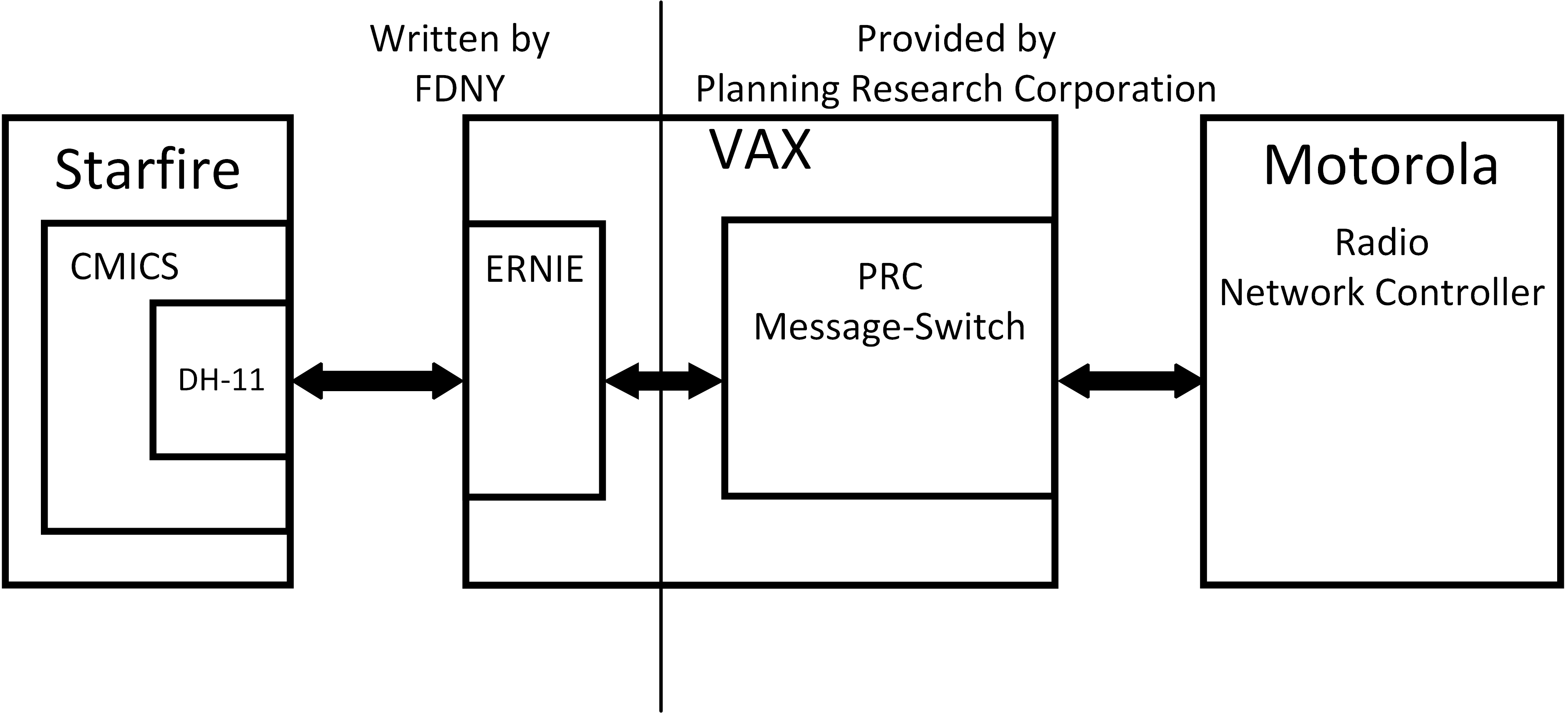
Figure 13 Starfire / VAX / Message-Switch / RNC
These CMICS modules each formed an essential link in the communications chain between a user-mode application on Starfire and the server on the VAX. Each handled the appropriate portion of the communications while also segregating the other modules. The design of the applications followed the existing system structure and the modules that supported the DV-11 which was the only other live link to systems outside Starfire other than the console.
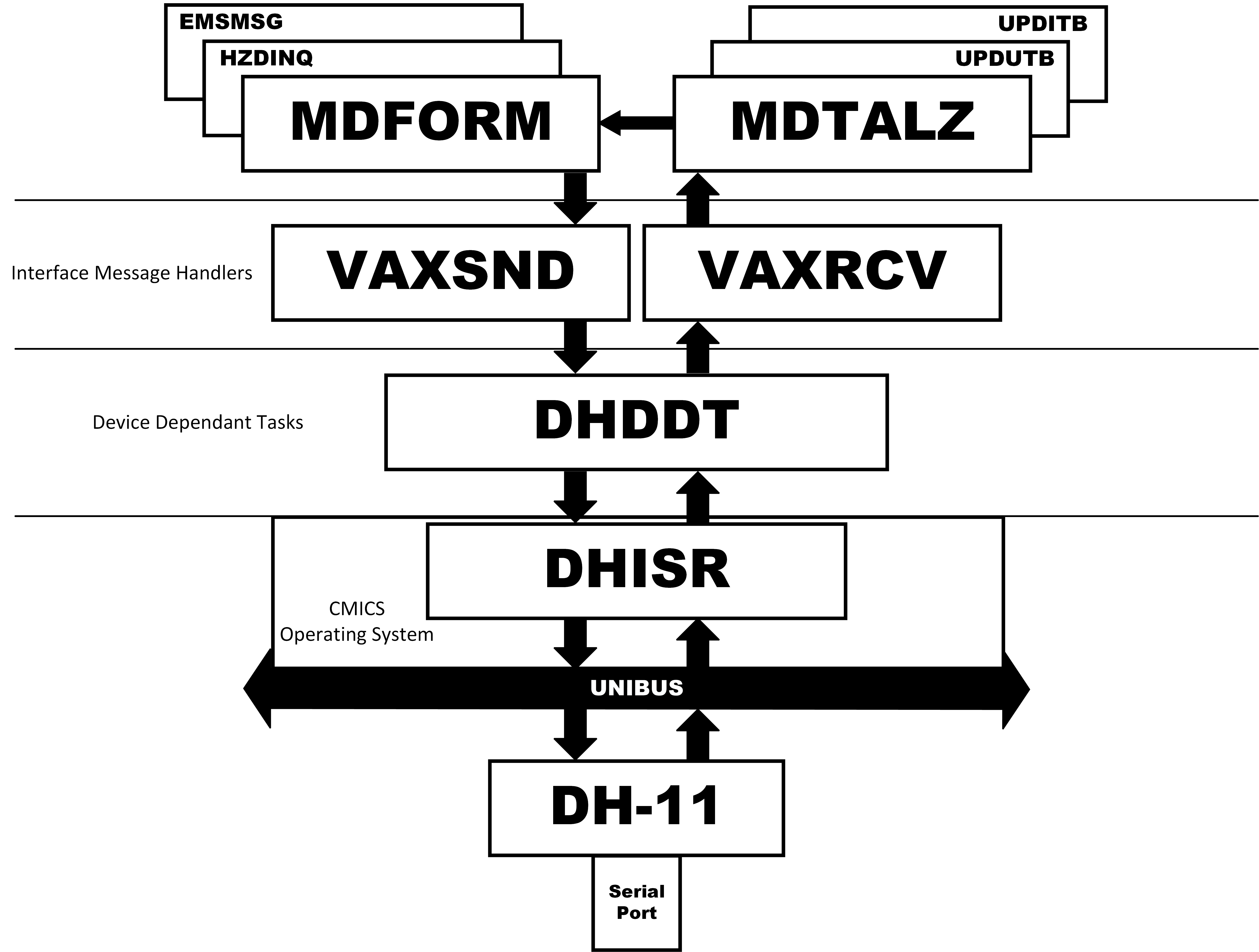
Figure 14 CMICS Application Stack
3.6.5.2.1 - Interrupt Service Routine (DHISR)
DHISR was the interrupt service routine that handled the serial port connected to the VAX. The DH-11 is a DMA device, meaning that once instructed to perform an I/O function, the OS was informed when the I/O had completed or some error condition had occurred. DHISR was the only module that accessed the DH device registers. Any process that needed to modify or read a DH register had to make a request through DHISR. Thus any such functions were implemented as part of DHISR functionality.
For receiving data from the VAX, the receive conditions would be set up. DHISR would be given a memory location to which the data would be written, and a maximum transfer size. DHISR would then issue the command to receive the data. It would then return control to the operating system. Once the transfer condition had been met, control would be passed to DHISR through the appropriate interrupt vector, which, in turn, would invoke DHDDT, informing that module that data had been received. DHDDT would know the location of the data transfer since it had passed that information to DHISR when the receive command was issued. DHISR would also inform DHDDT how many bytes had been transferred and on what port the transfer had taken place.
For transmitting data, DHISR would have received a transmit request from DHDDT. The request would include the memory location of the buffer that contains the data and the length of data that is to be transmitted. DHISR would give that address to the device through the device registers. DHISR would also give the device the length of the buffer to be transmitted. It would then issue the TRANSMIT command. After issuing the transmit command, DHISR would return control to the operating system.
DHISR was an integral part of the operating system executable and was loaded when the OS was loaded into memory.
3.6.5.2.2 - Device Dependent Task (DHDDT)
DHDDT was a privileged user-mode task that controlled the device through communication with DHISR. DHDDT would handle basic line discipline and cooperation with the program on the VAX that performed the same function. This includes establishing polling in both directions, and setting the link status to “UP” while receiving polls. DHDDT would also respond to operator commands to bring the link down “Logically”. This means that while polling was still working, no communications would be allowed across the link. DHDDT also performed the necessary monitoring function. While it was receiving polling it listed the link as up. If it missed three or more polls, it would mark the link down and prevent the sending of any further messages. Marking the link down would trigger additional events that caused notification to the computer operators and forced certain backup communication steps to be required.
DHDDT was responsible for initiating communications through the DH at system startup. It would send the appropriate commands to DHISR to initialize the device and enable the appropriate port. Since the interface was constantly polled and received polls from the VAX, DHDDT had to set up an input buffer, then pass the receive request command to DHISR specifying an input memory address, a receive buffer size, and a port number. DHDDT then had to set up a transmit buffer, build an outbound poll message, then pass the transmit request command to DHISR specifying an output memory address, a transmit buffer size, and a port number. DHDDT also set a timer that was used to initiate subsequent polls and check for the absence of inbound polls.
Following the standard set by the DV-11 communications protocol (DDCMP), the DH poll message contained certain link status bits such that system initiation status and operations commands could be communicated across the link with requiring distinct messages. The polling message included a length field of two bytes. For polls in the absence of any data, this field was zero. However, if there was actual data to be sent, the length field would include the length of the data message and the polling message doubled as the header of that message. When DHDDT processed an inbound poll that included a non-zero length field, it immediately established a receive buffer of the appropriate size then submitted a receive request specifying the memory address of the buffer, the length of the data to be received, and the port number.
When a user-mode program submits a transmit request to DHDDT, it will have received a resource number of the buffer that was built by the requesting program. This buffer will not have included the polling header, so DHDDT will build the polling header with the appropriate data length field, issue the transmit request for the poll, then immediately follow notification the that transmission completion by a request to transmit the user data. In this case, DHDDT will translate the resource number it received to a memory address, which it passes to DHISR in the transmit request.
I do not remember if I created a queue for transmit requests under CMICS. If so, it would have been DHDDT that would have handled this for both outgoing and incoming messages. Starfire had an extensive queuing facility but It was heavily merged into the system’s work-flow functionality and I avoided modifying this due to it’s complexity. I do remember that I wrote message queuing into the application that ran on the VAX.
3.6.5.2.3 - VAXRCV
VAXSND and VAXRCV formed the highest level of programming for the VAX Link. These two program were the ones that had actual communication with the other user-mode program. For instance, if DHDDT reported that the link has gone down, VAXRCV would initiate the various notification tasks; 1) a message to the system console, 2) change the status icon on the summary screen. VAXRCV also served as the switchboard for inbound messages. It delivered messages from the EMS dispatch system to the appropriate message handler for that source. In some cases, the message was from the administrative function of the radio system. If an outbound message to a MDT failed in it’s delivery, the radio console would report the failed delivery attempt, which VAXRCV would use to mark the terminal down, and initiate a notification that the unit may need to be notified through an alternate means. Conversely, the radio administrator may deliver a “Terminal Up” message. These are not taken as messages from the fire unit itself, but a message about the unit’s MDT. VAXRCV also processed each of the messages from the MDT’s and initiated any and all follow-on steps. It translated a MDT unit name to identify which unit the message had come from. If a startup message is received from an MDT and that unit is currently assigned to an incident, the application “MDFORM” invoked in order to build an appropriate dispatch ticket and send it to that MDT.
3.6.5.2.4 - VAXSND
VAXSND was the module that interacted with other user-mode programs that connected with DHDDT to implement the requests. One example is the command to bring the link down logically. The command from the operator would have been recognized in the module handling the operator console. Once the appropriate command had been entered, OPER would LINK to VAXSND. LINK was a synchronous interaction, meaning that the initiating program would be suspended while the LINK was being processed, to run again once the return from the LINK was reached. The trap to DHDDT from VAXSND is an asynchronous process, in that control is returned to VAXSND immediately upon receiving the request, rather than after the request has been processed. In this case, DHDDT would simply mark the link down logically and return to wait. Further attempts to transmit messages would be rejected by VAXSND.
In the normal case of transmitting a buffer, VAXSND would obtain a free memory buffer, copy the message into that buffer, initiate the trap to DHDDT passing the resource number of the new buffer, then exit, returning control to the requesting program. In this was there are no ownership issues with the initial buffer and the DH would not be accessing a buffer that may be modified by the requesting program.
3.6.5.2.5 - MDTALZ
In the normal case where a fire unit transmitted an operational signal to dispatch such as the signal that indicates they have arrived at the indicated incident location, or 10-84, VAXRCV will pass this message on the the program MDTALZ (MDT Analyze). A 10-84 signal results in a number of follow-on operational events, such as recording the signal in the incident history, informing the dispatcher, and the other responding units. Having received this signal from the unit’s MDT is handled similarly to when the same signal would have been entered for the unit by the radio dispatcher. Transferring the signal to MDTALZ marks the end of the processing within the new interface.
Another function of this module is to process the inbound messages properly depending on which model MDT the message has been received from. The keyboard layout differs between the two and correct meaning of each button is determined in this module.
3.6.5.2.6 - MDFORM
MDFORM is the program that builds and formats a message for consumption by a Mobile Data Terminal (MDT). In order that the information is presented to the fire officer in an efficient manner, the dispatch information is formatted specifically for the display device, which is forty columns wide and 23 rows high. Each MDT also has an attached thermal printer. There are two models of MDT and the messages need to be configured properly for each. Additionally, because it is important for the company officer to understand what operational state the dispatch system holds them in, there is a status window that always reflects the unit’s ambient status. The commands to keep this status window up-to-date are also formed and initiated in this module. A fire ticket is designed to be display on the terminals screen and print at the same time. Some messages are designated to be display visually but not printed, and some are destined to the printer only. Some messages are to automatically replace anything current displayed on the screen and some are allowed to be delivered to the saved messages buffer if there is something currently on the screen when the message is delivered. These actions are determined by the information in the MDT header which is built by this module.
3.6.5.2.7 - TM (Terminal Table)
TM is the terminal table that contains information about every MDT in operation. This information could have been added to the unit table, but in order to avoid increasing the size of that table, the unit table entry was increased only by one word which was a pointer into TM. The terminal entry included information about the MDT type, it’s ambient status, whether it had a printer attached and a pointer into the unit table for the unit the MDT was associated with.
3.6.6 - MDT Summary
When the Fire Department first investigated the possible implementation of MDT’s it’s impetus was the increasingly crowded voice radio system. The Department has been experiencing unit unavailability issues because units that were on-the-air and had just departed an active incident were not able to get air-time to report that they were available. Priority was given to units that were responding or reporting on incidents that were still in their growing phases. So units that had been released from an incident would wait to report this fact until they could get through and would hear about new incidents that they would have been assigned to if they had been marked available.
The MDT system was designed so that unit statuses could be reported and received by Starfire without using voice radio time. But the Department didn’t want the officers to be required to type a lot of information into the terminal, so the user interface was designed such that many signals could be submitted by hitting two buttons only, or maybe they had to type in one or two unit names before transmitting.
On the dispatch platform side, there was also a desire not to burden the dispatchers with interacting with the MDT system. This is why an inbound signal was eventually offered to Starfire just as if it had been entered by the radio or voice dispatchers and didn’t require their input to be memorialized and addressed.
All signals received by the system were written into the incident record using existing record designations, but with the signal source being “MDT”
The implementation include operational controls and monitoring that were used by the computer operations staff to ensure reliability
Only one project is demonstrates better than this one my complete mastery of the CMICS operating system and operating system concepts. Today the OSI model defines seven layers of the networking stack, the implementation for Starfire was much simpler but still incorporated four Layers
3.7 - UNISYS Summary Screens
The number of terminals available to Starfire was limited by the architecture 96. All of these were designated for a specific purpose and installed at specific locations. However, the number of people around the agency that could benefit from viewing active incident information was much larger than could be serviced with this number of terminals. FDNY had a mainframe system that it used for administrative purposes and terminals connected to that system existed throughout the city, and there was no practical limit to the number the system could support. The system was manufactured by UNISYS and implemented standard user accounting.
A project was initiated that would forward Starfire live incident information, known as a Summary Screens, to UNISYS so it could be duplicated and re-distributed to anyone who had proper privilege around the agency.
The challenge was that the only commercial communications protocol that Starfire hosted was DDCMP, which handled the data communications across synchronous circuits to the six concentrators. UNISYS did not support DDCMP on it’s communications controllers. But UNISYS did support IBM’s Bisync. The interface design chose Bisync to communicate between a Starfire concentrator and a UNISYS communications controller.
We used the standby central concentrator (A PDP-11/34) as a go-between. Using RT-11 running on the standby 11/34, we connected one of the CRT ports on the live concentrator to the one running RT-11. This was a simple asynchronous protocol for which I wrote a handler on an asynchronous port. The using one of the DV-11 synchronous ports, I implemented a Bisynch interface to the UNISYS communications Controller.
The software to consume the information and perform circuit traffic functions was written by Dr. Leo Tick PHD. Another FDNY developer, working in the UNISYS TIP environment wrote the software to display the summary screen on requesting UNISYS terminals.
This project demonstrates Operating System knowledge in that it required writing two device drivers. RT-11 did not include drivers for the DV-11 and did not natively support BiSync. I didn’t write device drivers in the formal sense in that the software I wrote did not become a part of RT-11. What I wrote was an application that ran under RT-11 that controlled one device through which the Starfire summary screen information was received, placed it in a buffer, than handed that buffer over to the DV-11 for transmission to UNISYS, using the BiSync Protocol. The software that interacted with the DV-11 had to respond appropriately to the line discipline that the UNISYS communications controller expected to see in order for that port to appear operational to the controller. It then had to put expected control characters on the line as part of the data transmission and respond to the acknowledgment from the receiver.
4 - Bibliography
1) Computer History Wiki. “RP06 Disk Drive.” August 15, 2024. https://gunkies.org/wiki/RP06_disk_drive.
2) Computer History Wiki “RS03/04 Disk Drive.” August 14, 2023. https://gunkies.org/wiki/RS03/04_disk_drive.
3) Farrell, Bob. The War Years. Independently published (August 2, 2021), 2021.
4) PDP-11/70 Processor Handbook. Digital Equipment Corporation, 1976. https://bitsavers.org/pdf/dec/pdp11/1170/PDP-11_70_Handbook_1977-78.pdf.
5) “KW11-P Programmable Real-Time Clock Manual.” Digital Equipment Corporation, October 1972. http://www.bitsavers.org/pdf/dec/unibus/DEC-11-HPWB-D_KW11P_Oct72.pdf
6) PDP-11 UNIBUS Processor Handbook. Digital Equipment Corporation, 1985. http://www.bitsavers.org/pdf/dec/pdp11/handbooks/EB-26077-41_PDP-11_UNIBUS_Processor_Handbook_1985.pdf.
7) Time-Line Computer Archive. “Digital Pdp11/70.” Accessed August 28, 2025. https://t-lcarchive.org/digital-pdp11-70/.
8) GeeksforGeeks. “Reentrant Function.” April 15, 2023. https://www.geeksforgeeks.org/cpp/reentrant-function/.
9) FireRescue1. “The ‘War Years’: A Brief History of the 1970s Fire Service,” February 7, 2022. https://www.firerescue1.com/firefighting-history/articles/the-war-years-a-brief-history-of-the-1970s-fire-service-sCJDDlDRpTL6JVb3/.
10) Crosby, Britton. “FDNY Riding with the Bravest, CapeCodFD.” FDNY Brooklyn Communications, March 29, 2001. https://www.capecodfd.com/pages%20special/FDNY9.htm
11) Johnson, Bob. Blackouts Bring down Starfire. Computer World, 1981. https://books.google.com/books?id=1REkdf3I86oC&pg=PA32&lpg=PA32&dq=Starfire+DIspatch+System&source=bl&ots=WMr4FMC-Dd&sig=ACfU3U3B2I2q2BfdgQ_FbI1yj10tsV50VA&hl=en&sa=X&ved=2ahUKEwjthYW-0rb9AhVZl4kEHf4XAug4RhDoAXoECAMQAw#v=onepage&q=Starfire%20DIspatch%20System&f=false.
12) Goldstein, Andrew. “Files-11 ODS-1 Specification.” June 19, 1975. https://bitsavers.org/pdf/dec/pdp11/rsx11m_s/Files-11_ODS-1_Spec_Jun75.pdf.
13) Bell, Gordon C, Craig J Mudge, and John E McNamara. Computer Engineering: A DEC View of Hardware Systems Design. Digital Press, 1978. https://bitsavers.org/pdf/dec/_Books/Bell-ComputerEngineering.pdf.
14) Gunkies.org. “CR11 Card Readers.” February 3, 2021. https://gunkies.org/wiki/CR11_Card_Readers.
15) Chirgwin, Richard. “Nuke Plants to Rely on PDP-11 Code UNTIL 2050!” The Register, June 19, 2013. https://www.theregister.com/2013/06/19/nuke_plants_to_keep_pdp11_until_2050/.
16) Stallings, William. Computer Organization and Architecture. 11th ed. Pearson, 2018. https://www.pearson.com/en-us/subject-catalog/p/computer-organization-and-architecture/P200000003394/9780134997193.
17) PDP-11 MACRO-11 Language Reference Manual. Digital Equipment Corporation, March 1983. http://www.bitsavers.org/www.computer.museum.uq.edu.au/RSX/AA-V027A-TC%20PDP-11%20MACRO-11%20Language%20Reference%20Manual.pdf
18) “DV-11 Communications Multiplexer.” Digital Equipment Corporation, December 1976. http://www.bitsavers.org/www.computer.museum.uq.edu.au/pdf/EK-DV11-OP-001%20DV11%20Communications%20Multiplexer%20User's%20Manual.pdf
19) AA-H266A-TC_RSX-11M_V3.2_Task_Builder_197906. Digital Equipment Corporation, June 1979. https://bitsavers.org/pdf/dec/pdp11/rsx11m_s/RSX11M_V3.2_Jun79/3A_ProgramDevelopment/AA-H266A-TC_RSX-11M_V3.2_Task_Builder_197906.pdf
20) Tanenbaum, Andrew S., and Herbert Bos. Modern Operating Systems. 4. ed. Prentice Hall, 2015.
21) Cruz, Frank. “The IBM 3270.” Columbia University Computing History, March 27, 2021. https://www.columbia.edu/cu/computinghistory/3270.html.
22) Young, Michelle. “NYC’s Fire Alarm Call Boxes: Everything You Wanted to Know.” Untapped New York, May 9, 2024. https://www.untappedcities.com/nycs-fire-alarm-call-box
23) “Fire Alarm Telegraph Bureau, Bronx Central Office.” NYC Landmarks Preservation Commission, June 13, 2023. https://s-media.nyc.gov/agencies/lpc/lp/2668.pdf
24) Staff, Fire Engineering. “Computerized Dispatching in Brooklyn.” Fire Engineering: Firefighter Training and Fire Service News, Rescue, April 1, 1978. https://www.fireengineering.com/firefighting-equipment/computerized-dispatching-in-brooklyn
25) Swersey, Arthur, J. “Reducing Fire Engine Dispatching Delays.” The New York City RAND Institute, December 1973. https://www.rand.org/content/dam/rand/pubs/reports/2006/R1458.pdf
26) “RH70 Special Massbus Controller.” Digital Equipment Corporation, February 1977. https://bitsavers.org/pdf/dec/unibus/CSS-MO-F-5.2-27_RH70_Option_Description_Feb77.pdf
27) “WD Blue 3.5-Inch SATA PC HDD.” Western Digital, March 2025. https://documents.westerndigital.com/content/dam/doc-library/en_us/assets/public/western-digital/product/internal-drives/wd-blue-hdd/product-brief-western-digital-wd-blue-pc-hdd.pdf
28) “DH-11 Asynchronous Multiplexer.” Digital Equipment Corporation, September 1976. http://www.bitsavers.org/pdf/dec/unibus/EK-ODH11-OP-002_DH11_Asynchronous_16-line_Multiplexer_Users_Manual_Sep76.pdf
29) “DDCMP Message Protocol.” Digital Equipment Corporation, March 1978. http://www.bitsavers.org/pdf/dec/standards/EL-00121-00_A_DEC_STD_121_DDCMP_Mar78.pdf
5 - Table of Figures
Figure 1 Starfire Central System
Figure 2 Starfire High Level Configuration
Figure 3 Typical Borough Configuration
Figure 4 PDP-11/70 Configuration
Figure 5 PDP-11/84 Block Diagram
Figure 6 Performance/Functionality versus Price
Figure 7 BARS and ERS Boxes
Figure 8 Brooklyn Decision Dispatcher Position
Figure 9 Brooklyn Radio Dispatcher Position
Figure 10 Alarm Teleprinter/Selector
Figure 11 CMICS Structure
Figure 12 Task Structure
Figure 13 Starfire / VAX / Message-Switch / RNC
Figure 14 CMICS Application Stack
6 - Table of Tables
Table 1 Interrupt and Trap Vectors
Table 2 Device Addresses
Table 3 FloatingInterruptVectors
Table 4 Floating Addresses
7 - Additional Reading
1. Kaiser, Charles. “Brooklyn Firemen Use New Computer And Handle Alarm Calls Faster.” Archives. The New York Times, August 30, 1977. https://www.nytimes.com/1977/08/30/archives/brooklyn-firemen-use-new-computer-and-handle-alarm-calls-faster.html.
2. Mohan, John, and Michael Geller. “AN ENVIRONMENTAL SIMULATOR for the FDNY COMPUTER AIDED DISPATCH SYSTEM.” 1976. https://www.academia.edu/9875249/An_Enviromental_Simulator_for_FDNY_Computer_Aided_Dispatch_System.
3. Crosby, Britton. “FDNY Riding with the Bravest, CapeCodFD.” FDNY Brooklyn Communications, March 29, 2001. https://www.capecodfd.com/pages%20special/FDNY9.htm
4. Walker, Warren E., ed. Fire Department Deployment Analysis: A Public Policy Analysis Case Study. Publications in Operations Research Series 2. North Holland, 1979.
5. Mohan, John, Fire Engineering. “Computer Aided Dispatch Becomes $15 Million Reality in New York City.” Fire Engineering, October, 1980. https://www.fireengineering.com/firefighting/computer-aided-dispatch-becomes-15-million-reality-in-new-york-city/
6. Staff, Fire Engineering. “Computerized Dispatching in Brooklyn.” Fire Engineering: Firefighter Training and Fire Service News, Rescue, April 1, 1978. https://www.fireengineering.com/firefighting-equipment/computerized-dispatching-in-brooklyn/
7. Singer, Michael. PDP-11 Assembler Language Programming and Machine Organization. Wiley, 1980.